Have you ever been so taken aback by the structure of a question that your first thought is, “say what? Did they really just ask me that?” In the vernacular-sensitive world of utility pipelines, it happens more often than you might think.
One recent example that comes to mind was a customer saddled with what to do about a pipeline system under construction that could experience as high as 400-psi internal water pressure in-service. Yet, the test pressure is set at just 200-psi, based on a “weakest link” parts presumption. There is no way to design a reliable system with only this minimal and relatively uncertain information known.
Fortunately, asking the right questions early on will guide all to properly applying materials and concepts. So, what are these questions that need to be addressed? Let’s begin with outlining some basic concepts and comparisons that serve to frame the discussion:
Product Realities
Given the superior strength and maximized inside diameters throughout the nominal range of production, Ductile iron pipe is rarely, if ever, the “weakest link” in a system. That said, if any part of a system might experience elevated pressures, every material in that part must be capable of repeatedly handling these elevated pressures over time. Ductile iron pipe (DI pipe) and fittings will always meet that need.
Hydraulic Fundamentals
So just where do these pressures come from? Internal fluid pressure is created either by elevation changes along the system and/or pumps within the pipeline system. As we know, every Ductile iron pipe manufacturer “creates” a minimum of 500-psi of internal pressure within each pipe as a means of material inspection during the finishing process, in all sizes 3-inch through 64-inch diameters, with the pipe laying essentially level and the water not moving within it, while pressure is built via pumps, i.e., the hydrostatic test per ANSI/AWWA C151 latest edition. Hence, it can be stated that diameter alone has no direct effect upon internal pressure … but more to come about that later.
The other primary way that pressure is created is from “stacked water.” Every vertical foot of a water column (elevation change) creates or reduces the pressure by 0.433-psi. Therefore a 100-foot elevation change is equivalent to 43-psi. This is known as static head.
Dynamic head is pressure changes created by variations in water velocity through the pipe. For DI pipe, that equates to approximately a 50-psi increase or decrease for each 1-foot per second (fps) change in flow velocity. Dynamic head does not affect static head. It is essentially added above static head yet cannot ever reduce the static head.
A Working Pressure of 400-psi?
Appropriate questioning revealed this pipeline would be transporting water from a well to an elevated reservoir. It takes just a 924-ft elevation change from the bottom of the well to the top of the reservoir miles away to create a 400-psi requirement. Daily usage from the reservoir varies, but the anticipated flow to the reservoir is 2 million gallons per day (mgd). The process to determine the most efficient pipe diameter may now begin.
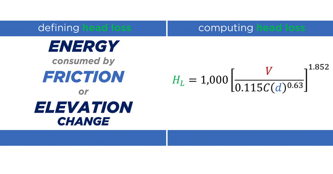
While diameter alone does not determine pressure and/or capability, the combination of velocity and head loss created determines the system’s efficiency. The diameter is a significant variable in computing both of those values. A couple of methods to transport the water volume required while maximizing the system’s efficiency might be to increase the pipeline diameter or install a dual-line. Increasing the size of the pipe may appear expensive in the short term yet may substantially save on operational costs over the life of the system, especially in an area of future population growth.
McWane Ductile provides an excellent tool for analyzing flow via the McWane Pocket Engineer app found at pe.mcane.com. Regardless of diameter, the targeted velocity range in feet per second (fps) of any system is from 3-fps to 10-fps, with 5-fps being the typical design velocity of daily peak flows.
Velocity Matters
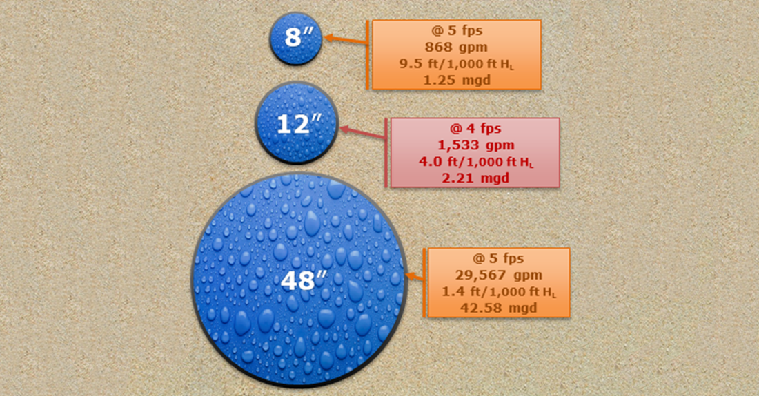
For an 8-inch class 350 Ductile iron pipeline moving water at 5-fps through the 2-mile (10,600-ft long) pipeline to the uphill reservoir, the Pocket Engineer calculates a flow rate of 868-gallons per minute (gpm) and a head loss of 9.5-feet per thousand feet (ft/1,000-ft, or psi consumed), delivers 1.25 mgd, which is short of the 2.00-mgd design requirement.
Note that just 100-psi of the pump power (friction loss through the pipe) would be consumed using 8-inch pipe. At a top-end velocity of 10-fps, while delivering 2.50-mgd, which is more than the design need, the flow rate updates to 1,736-gpm, and the head loss increases to 34.3-ft/1000-ft of pipe, consuming 364-psi of pump power, which is by no means or measure efficient.
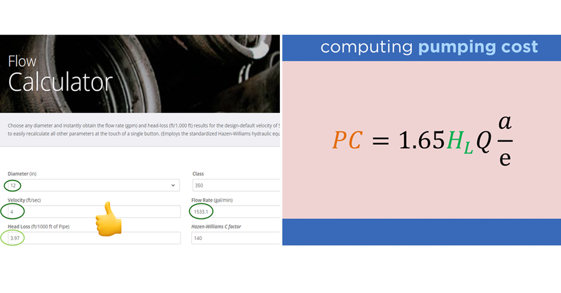
The choice then becomes to operate at those extreme parameters or utilize the option to upsize the pipe diameter for greater operational efficiency, especially regarding pumping costs. Increasing the pipe diameter to 12-inch will ensure the desired volume while decreasing strain (i.e., pump burden) and reducing operating costs (i.e., kilowatt energy dollars) over the system's expected life. A 12-inch class 350 pipe with a velocity of 4-fps will supply 2.21-mgd with a head loss of just 4-ft/1,000-ft of pipe, equating to only 42-psi of pump power being consumed by the 2-mile travel through the pipeline.
Install Parallel Lines?
This option may seem expensive or cumbersome in the short term but can increase the long-term return on investment when required volumes of flow rise to much larger levels, say 43-mgd or more, which is not unusual for a city or highly populated town. This volume of water could be delivered in 24-hours through a 48-inch class 350 DI pipe at 5-fps. Dual 30-inch class 350 pipelines operating at 5-fps would transport 17-mgd each or 34-mgd total.
Likewise, dual 36-inch pipelines at 5-fps would bring 24-mgd each or 48-mgd total. All these present reasonable head loss results meaning the final choice is entirely designer preferential. The diameter-combination options can be endless and highly creative. Additionally, one of the parallel lines may remain in operation while maintenance is completed on the other.
Hydrostatic Helpers
Hydrostatic test pressure at 200 psi for a 400-psi system? Not a good idea. Hydrostatic testing of newly installed pipelines is clearly outlined in the ANSI/AWWA C600 standard - Installation of Ductile Iron Mains and Their Appurtenances Sec. 5.2 The test pressure shall not be less than 1.25 times the stated working pressure of the pipeline measured at the highest elevation along the test section and not less than 1.50 times the stated working pressure at the lowest elevation of the test section.

Therefore, if the working pressure were 400 psi, the test pressure at the lowest point would be 600-psi. Safety concerns are apparent, and every effort to mitigate line pressures to acceptable levels is in the best interest of all parties involved.
Excessive pressures, as previously discussed, will most definitely expose the weakest link. Hopefully, pressure ratings of all the components intended for the system have been researched during the design phase. The good news is the most conservative design parameters in the industry, including a safety factor of 2 to 1 and an additional allowance of 100-psi for surge flows, belong to Ductile iron pipe.
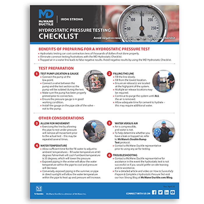
With this free Hydrostatic Pressure Test Preparation Checklist from McWane Ductile, you can avoid negative test results and succeed the first time!

Summary
Water professionals may, at times, know what they want or need but may not know the right questions to ask. What began with a question regarding pressure and diameter lead took a somewhat different road to the finish. The parameters discussed in this blog on the onset may appear extreme and unusual. However, there are many applications such as this throughout North America.
You have the questions; we have the answers. Reach out to your local McWane Ductile representative, or check out the Ditch Doctor section at McWaneDuctile.com for more intriguing Q & A!

