The Purpose of Spigot Stripes
Spigot stripes are used as a guide for assembly and a deflection check after assembly. Pipelines are not always designed in a straight line. It is often necessary to deflect pipe from a straight line to follow the curvature of streets and roads both vertically and horizontally. Ductile iron pipe is well suited for joint deflection.
When you receive your shipment of ductile iron pipe, you will notice there are stripes on the spigot end. These stripes are there to:
- Help the installer know how deep to push the spigot into the bell of the pipe.
- After the pipe is assembled, they can be used as a guide for joint deflection.
Assembly
When assembling ductile iron pipe, the spigot end should be aligned and carefully pushed into the socket. Depending on the size of the pipe, this can be accomplished with a crowbar, backhoe bucket, or even a come-a-long when assembling in a tight location.
For all Tyton® Joint pipe, there will always be two stripes on the plain end. This will help to identify the bell type in the field.
When the spigot end is fully inserted, the first painted stripe will disappear and the second stripe will be flush with the face of the bell.
- Note: Pipe with a Fastite joint will have only one spigot stripe on the plain end. Tyton® and Fastite pipe are considered compression joints and the gaskets for these two joints are not interchangeable.
Take care when assembling the pipe not to slam the spigot end into the bell of the pipe. This could cause damage to the cement lining at the back of the bell.
Deflection Capability
Pipelines are not always designed in a straight line. It is often necessary to deflect pipe from a straight line to avoid existing obstructions or to follow the curvature of streets and roads both vertically and horizontally. Ductile iron pipe is well suited for joint deflection.
When following the curvature of streets and roads, the trench should be excavated wider than normal to allow for straight line assembly both vertically and horizontally, before deflection is made.
Non-restrained Tyton® Joint pipe, often referred to as “push-on” joints, in size 3-inch - 36-inch has a maximum allowable joint deflection of 5 degrees.
To achieve 5 degrees deflection, an 18 foot nominal LL pipe can be moved up to 19 inches from the centerline in any direction needed. Some contractors will run a measuring tape from the pipe centerline to a preplaced survey stake to achieve the deflection limits. In some cases, project plans may limit the allowable deflection to only 75 percent of the products maximum capability.
After desired deflection is achieved, continue with the installation of the pipeline and deflect as specified per plans or terrain.
Tyton® Joint with Sure Stop 350®
When installing Tyton® Joint pipe with a Sure Stop 350® gasket, assemble as recommended above. Be sure to keep the joint in straight and level alignment during assembly. Once complete, pull back to set the teeth in the gasket and actuate the restraint mechanism on the pipe.
Once the teeth are set, joint deflection can be achieved. Be careful not to exceed the maximum recommended deflection of of up to 5 degrees.
Deflection Limits using TR Flex®
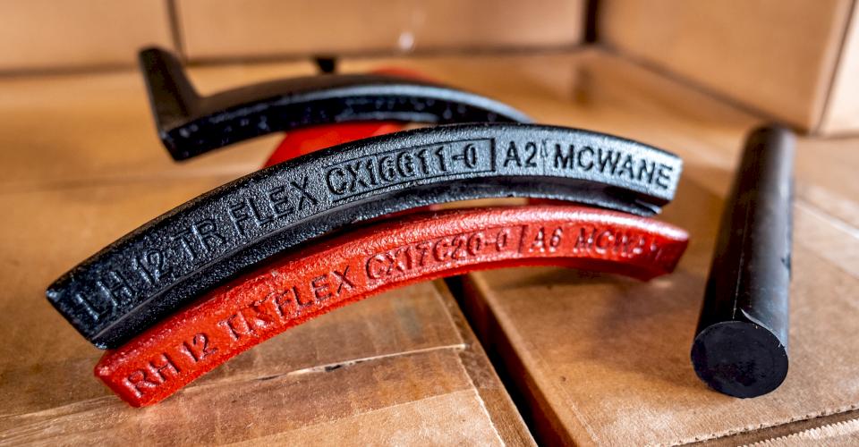
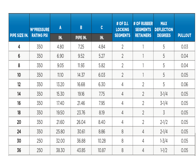
TR Flex® pipe is assembled like a conventional Tyton® Joint until the first spigot stripe is in the joint socket. Keeping the joint straight, insert the locking segments and place the rubber retainers to keep the locks in place.
After the joint is assembled, it needs to be extended to minimize growth or extension of the line when it is pressurized.
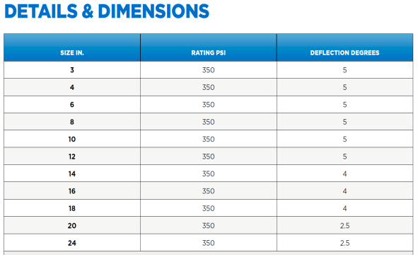
Once the joint has been extended, you may then set joint deflection, but remember not to exceed recommended maximum deflection of up to 5 degrees depending on pipe diameter.
Mechanical Joint Pipe Deflection
Mechanical Joints also have a maximum allowable degree of deflection for a full length of pipe which varies by size from 7 degrees (6-inches) to 2 degrees (24-inches). Follow the chart for maximum deflection with mechanical joint pipe.
Ductile vs. PVC
With PVC or plastic pipe, care must be taken not to exceed the recommended deflection limits of the pipe or serious stress and breakage can occur, which can result in dangerous consequences in the field.
The McWane Pocket Engineer
A resource that follows the AWWA C600 standard to compute the tightest radius achievable without the use of fittings is the McWane Pocket Engineer Radius Calculator which can be found at pe.mcwane.com.
For example, if you enter 12-inch Tyton® Joint into the Radius Calculator it will immediately supply you with the following information:
- Nominal pipe length as-cast (ft) 18.18
- Deflection per joint (deg) 5.00
- Deflection available per pipe length (in) 19.09
- Minimum radius achieved (ft) 208.2
This app provides quick access in the field to product submittal sheets specific to the joint and size of pipe you are installing.
For additional references and information, you may also visit our website at http://www.mcwaneductile.com/learning-center/submittal-sheets/ to learn more.
As another handy source of information in the field, you may also turn to the Installation Guide for Ductile Iron Pipe published by DIPRA, and also viewable on the McWane Pocket Engineer.
Need Assistance With Your Waterworks Project?
McWane Ductile offers multiple services to our customers extending far beyond manufacturing DI pipe. From estimating to design, from production to installation, we take great pride in providing education and assistance to water professionals throughout the water industry.
Check out all our digital offerings:


