Straight-line distances can sometimes be deceiving when examining a set of plans for a water or sewer project. This #IronStrong Blog will address how to determine the exact amount of Ductile iron pipe (DI pipe) needed when a change of direction due to horizontal offset fittings occurs.
Why is it Important to Calculate Change of Direction?
Pipeline designs should always account for thrust forces at each change in direction. The most common approach is utilizing Mechanical Joint fittings with wedge action retainer glands and Tyton® Joint pipe with locking gaskets. The key component here is that the joints of pipe that fall between the fittings can easily be cut in the field to the desired length and inserted into the mechanical joint fitting. That said, you should still know how to calculate the distance of those joints, as we all know it is best to “measure twice and cut once” when assembling anything during a construction project.
When utilizing TR Flex® Restrained Joint fittings along with TR Flex® Restrained Joint Pipe, the distance between offsets becomes critical as the pipeline joints leading up to and between the fittings must be manufactured to specific lengths for the fittings to connect similar to a jig-saw puzzle.
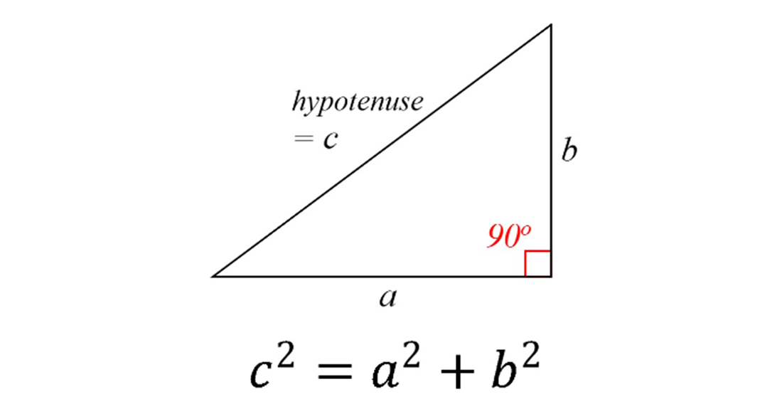
The Pythagorean Theorem (a²+b²= c²)
This equation calculates the distance between two fittings in a horizontal plan. The Pythagorean Theorem equation is used to assist in finding the length of the line in the right triangle when you already know certain distances. Let’s take a closer look.
Based on the diagram below, when applied to a set of pipeline plans, we will calculate the distance of “c,” or the actual center-to-center distance between two offset fittings.
You can easily figure out the length “c” by finding “a” and “b” based on the scale and distances shown on the plans. The x-axis (“a”) is the direction in which the line is traveling or the run of the line. The y-axis (“b”) is the change in direction of the line to the left or right.
Horizontal distance between fittings and offsets (Plan Layout)
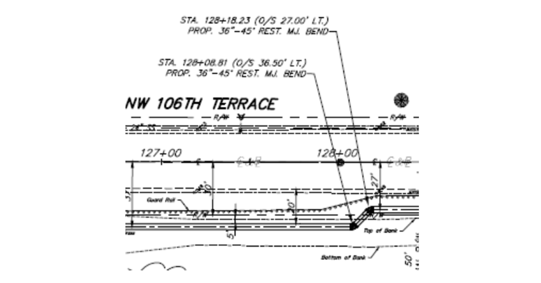
Let us work through a simple example using the above diagram.1 We are looking at a 36” Watermain with two 45° fittings and need to calculate the actual horizontal distance between them, or the value of “c.“ The diagram below illustrates how we calculate each variable to determine the distance, center-to-center, between two offset fittings.
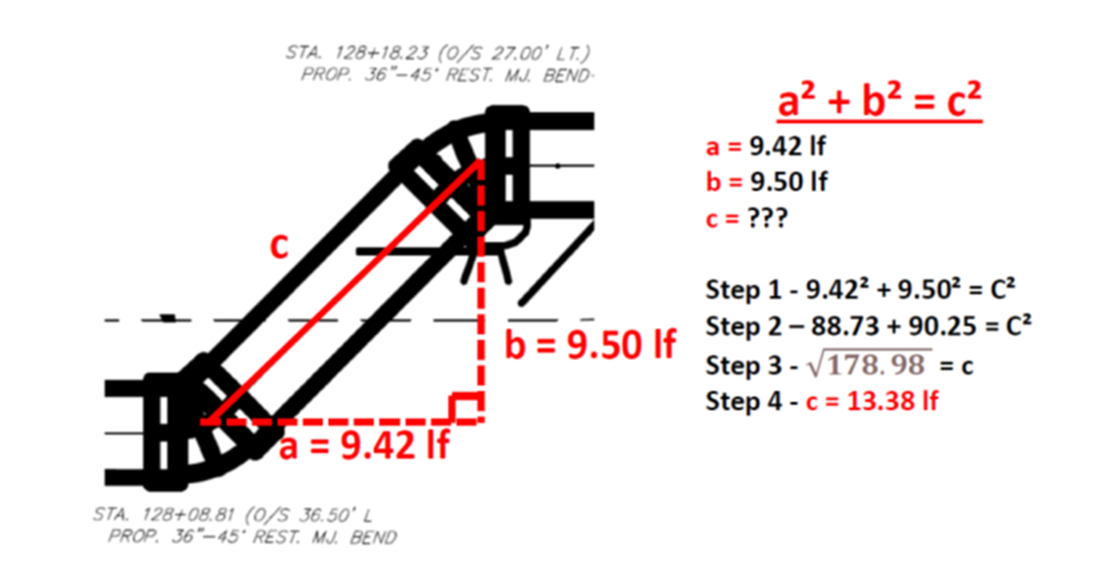
So now we know the distance between the two 45° Bends is 13.38 lineal feet, but how did we get here?
We arrived at the distance of “a” to be 9.42 lineal feet, as that is the actual straight-line distance derived from the station numbers shown on the plan page. (Sta #1 128+08.81 to Sta #2 128+18.23)
The “b” distance is equal to 9.50 lineal feet. This number is calculated by looking at the distance between the “offset from center” measurements shown on the plans. (Sta #1, O/S 36.50’ L to Sta #2, O/S 27.00’ LT)
Now that we have values for “a” and “b,” we can calculate the distance between the two 45° bends, or the “c.”
As shown in our diagram above, we take our “a” (9.42) and square it to arrive at 88.73. Next, we take our “b” (9.50), square it, and arrive at 90.25.
88.73 + 90.25 = c²
To solve our equation for c², we must add the left side of the equation together and then take the square root of that number. In other words, 88.73 + 90.25 = 178.98, and the square root of 178.98 is equal to 13.38, which is the value of the “c,” our center-to-center distance between the two fittings.
Key considerations within a set of plans to determine the distance of a horizontal offset.
You may encounter various deviations from plan set to plan set. Below are a few more common ones to become familiar with when calculating the distance.
- The Baseline – most plans follow along a set of station numbers to assist in straight line distances. At times, there will be a “Baseline” on the plans. The "baseline” may follow the center of a road, right of way, or some other location. If there is a “baseline”, you will need to determine if the horizontal change of direction passes from one side to the other of this baseline. If so, you will need to utilize the baseline as “the center” and be sure to account for the horizontal change in direction on both sides of that center line. Commonly, the station numbers will be called out with “LT” or “RT,” indicating the distance on the left or right side of the baseline.
- Plan view —The plan view scales are the same regardless of whether it is the horizontal run (“a”) or a change in directions (“b”).
- Why is this calculation important? This is a very important part of estimating, bidding, and purchasing because if you simply base the distance between offset fittings on the straight-line distances, as shown on the plan pages, you will typically come up short. When it comes to actually calculating the distance for installation, you will need to subtract the lay lengths of both fittings from the calculated “c” distance.
Conclusion
This Iron Strong Blog has examined how to calculate the horizontal lay length of an offset in the plan view using the Pythagorean Theorem, with no change in elevation between fittings. If you do not want to do the math, you may find a right-angle triangle calculator on the internet and bookmark it to do the math for you. Look for additional information to be shared on calculating distance and angle topics in a future Iron Strong blog.
Need Assistance with Your Waterworks Project?
If you have any questions regarding your water or wastewater infrastructure project, your local McWane Ductile representative is equipped with the expertise to assist you. Many of our team members have managed small and large water utility systems, served in engineering consulting firms, and bring decades of experience solving field issues involving pipeline construction and operation. From design to submittal to installation, we strive to educate and assist water professionals throughout the water and wastewater industry.
Check Out All Our Digital Offerings
- More articles and videos from our Iron Strong Blog
- Training Opportunities with McWane Ductile
- The McWane Pocket Engineer
- Engage with us on LinkedIn
- Subscribe to our YouTube Channel
- Follow us on Facebook
- Follow us on X
References
-
Miami-Dade Water andReferences Sewer Department Utility Pipeline Engineering & Construction Division, 3071 SW 38th Avenue, Miami, FL 33146 – “Furnish & Install 36-Inch Ductile Iron (D.I.) Water Main Along NW 106th from NW 107th Ave. to NW South River Drive PCTS No. 12426, ER No. W016923”

