When I first started my engineering career, I was placed in charge of coordinating the relocation of water transmission and distribution pipelines to accommodate the construction of an interstate highway through a city of approximately 180,000 residents. Many times, these projects required pre-poured thrust block restraints due to the amended connections between new and old waterlines in a short timeframe so as not to leave customers inordinately out of water for long periods of time.
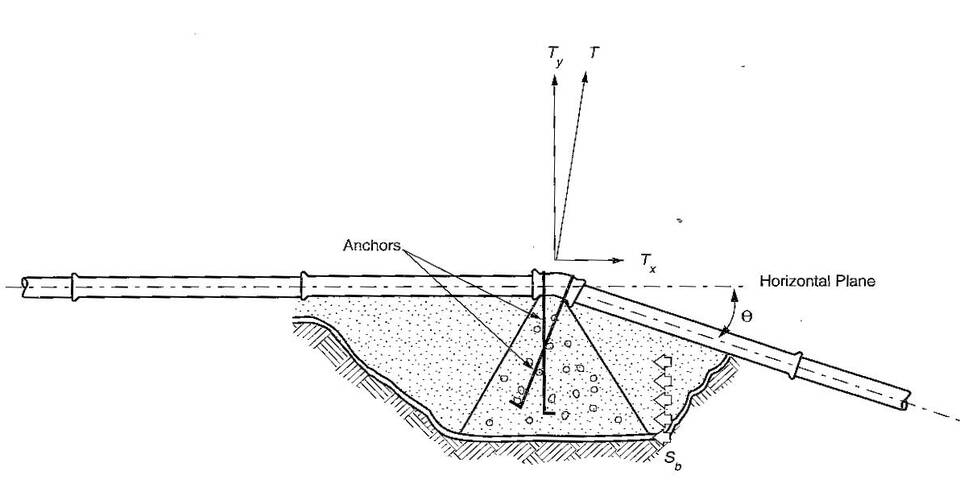
One thrust block I designed on a 48-inch pipeline was larger than the size of the bedroom in my first house! Thrust blocks have been used effectively to restrain fittings on water pipelines for many decades, and in fact, are still utilized today. However, my experience in the field has seen the use of thrust blocks alone as a possible liability to the utility.
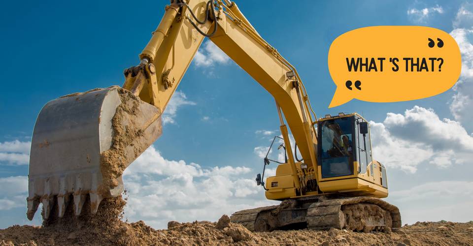
“What’s that?” the backhoe operator of a company not associated with the water utility yells while he continues to dig in behind some concrete “obstruction” in the ground. You guessed it ─ a thrust block restraining a fitting on a waterline. In just a matter of minutes, the undisturbed earth placing pressure against the concrete thrust block is now disturbed or non-existent. The fitting blows off… and I’m sure you can picture the scene afterward. Even though the use of thrust blocks has been effective over the years, many disruptions can occur for various reasons.
A New and Improved Way
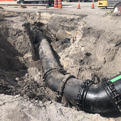
THE GOOD NEWS…there are very effective and proven modern products available to provide a restraint system for your Ductile iron pipeline project. Basically, these systems rely on the friction of the soil against the pipe to hold fittings and other appurtenances in place. Because this is not a "point source" restraint system, but one that is essentially comprised of the pipe itself, disturbances that can fail the system are unlikely to happen. Due to significant safety factors involved in the proper design of such, most restraint joint pipelines often survive even a near-total abandonment of the original surrounding soil during washouts or other land movement events.
McWane Ductile’s TR-Flex® Restrained Joint Pipe has proven to be very effective in cases such as Horizontal Directional Drilling, Bridge Crossings, and areas of suspected earth movement, etc., in resisting forces that could culminate in failure with other joint systems or pipeline materials. In addition to providing the needed restraint in situations just noted, TR-Flex Restrained Joint Pipe is very easy to assemble.
Effectively, the joint goes together much like Tyton® Push-on Joint Ductile iron pipe, with much efficiency gained during the construction process compared to other restraint systems that require the tightening and proper torquing of many bolts. See more on this topic; What is TR Flex Pipe and How is it Assembled? by my colleague, Dan Flaig.
The Basis of Restrained Joint Pipe Performance
Ductile iron pipe and fittings are most often joined with push-on or mechanical joints. Neither of these unrestrained joints provides significant resistance against longitudinal separation other than the minimal compressive-frictional force between the rubber gasket and the plain end of the pipe or fitting. Tests have shown that this frictional resistance in the joint is unpredictable, varying widely with installation conditions and other factors that are insignificant in other respects.
Thus, these joints should be considered as offering no longitudinal restraint for design purposes. At many locations in an underground or aboveground pipeline, the configuration of the pipeline results in unbalanced forces of hydrostatic or hydrodynamic origin that, unless restrained, can result in joint separation.
For instance, regardless of diameter or joint type, if above ground, the pressure exerted by just 50-psi of internal hydrostatic pressure is typically enough to gently separate the joint longitudinally without the aid of the weight of the earthen cover, friction from soils, or a dedicated restraining mechanism upon the joint.
Generically, these unbalanced hydrostatic and hydrodynamic forces are called Thrust Forces. In the range of pressures and fluid velocities found in waterworks or wastewater piping, the hydrodynamic thrust forces are generally insignificant in relation to the hydrostatic thrust forces and are usually ignored. Simply stated, thrust forces occur at any point in the piping system where the direction or cross-sectional area of the waterway changes.
Thus, there will be thrust forces at:
- bends
- reducers
- offsets
- tees
- wyes
- dead-ends
- and valves
An alternative method of providing thrust restraint in lieu of thrust blocks is the use of restrained joints. A restrained joint is a special type of push-on or mechanical joint designed to provide longitudinal restraint. Restrained joint systems function in a manner similar to thrust blocks, insofar as the reaction of the entire restrained unit of piping with the soil balances the thrust forces. The objective in designing a restrained joint thrust restraint system is to determine the length of pipe that must be restrained on each side of the focus of a thrust force.
This will be a function of:
- the pipe size
- the internal pressure
- depth of cover
- the characteristics of the soil surrounding the pipe
- and whether the pipe is polyethylene encased
The thrust force must be restrained or balanced by the reaction of the restrained pipe unit with the surrounding soil.
The source of the restraining forces is twofold:
- the static friction between the pipe unit and the soil
- the restraint provided by the pipe as it bears against the sidefill soil along each leg of the bend
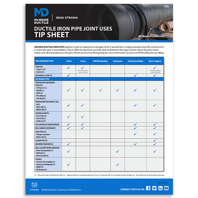
Is it the right Ductile iron pipe joint for the job? Be sure with this free and handy tip sheet listing various DI Pipe joints and their uses from McWane Ductile!
DOWNLOAD NOW
Correct Criteria = Proper Design = Lasting Pipelines
Although I am an engineer, I would find my wife asking the question on the afternoon of Christmas day, “Did you read the instructions?” This, of course, was while I was complaining about having some random part or too many screws left over after assembling one of my daughter's Christmas gifts. THE RESULT? Either the item I assembled did not work properly, or I had to go back and redo what I thought I had already done.
The M41 Manual of Water Supply Practices for Ductile Iron Pipe and Fittings published by the American Water Works Association (AWWA) details the engineering foundation of pipe restraint using Ductile iron pipe and outlines in detail those engineering, soil mechanics-based formulas that should be utilized in designing these restraint systems. Illustrations, charts, tables, and formulas relating to this subject can be found on pages 85-147 of the Third Edition of AWWA's M41 Manual. Using this approach in designing various Ductile iron pipe restraint systems has proven successful over the past many years using the method as noted above, which was developed by water professionals as shown in the manual.
When one chooses “not to follow the instructions” put forth in the M41 Manual, the possibility of inefficient or ineffective design arises. Performing a restraint system design using an approach pertaining to another pipe material may find the result as either over-or under-designed. Because of the success throughout history all over the country in designing restraint systems using Ductile iron pipe utilizing the M41 manual approach, it stands to reason this should be the gold standard for design.
The Good News — It's Easy
In examining the complex engineering equations found in the M-41 manual explanation, it becomes apparent that a meticulous approach has been utilized in determining restraint length values. However, computer software has been developed to assist water industry professionals in determining these values.
The McWane Pocket Engineer is a unique tool that can be downloaded free of charge. Contained in the pocket engineer is a set of calculators, one of which relates to the lengths of restrained joint pipe necessary to hold in place appurtenances of various sizes, configurations, etc. This calculator has been developed utilizing the equations noted earlier found in AWWA’s M-41 Manual. All that is needed are a few variables about that particular pipeline design—then push a button.
Thoughts on Combining Thrust Blocks and Restrained Joints
Combining restrained joints and thrust blocks by designing each system independently and then incorporating both into the piping system would seem to yield the most significant degree of security. It is often poor practice to mix systems based on each system being designed to resist a percentage of the resultant thrust force.
Both thrust blocks and restrained joint pipe systems require slight movement before their respective thrust restraint capability can be developed. Those movements must be compatible for the combination to be successful. Because of the uncertainties of the degree of these movements being compatible, you must give this design approach special consideration.
Considering Future Excavations
One concern of those responsible for infrastructure pipeline design, installation, and maintenance is the possibility of substantial excavation in the close vicinity of previously installed restrained pipe and fittings, including parallel excavations. Remembering the usual function of restrained pipes in transmitting thrust forces to the soil structure, it is obvious that if this structure is removed or significantly disturbed with the pipeline under pressure, the safety and stability of the system may be compromised.
In this regard, it would seem reasonable to temporarily shut down nearby existing restrained lines to do such work or conduct such operations during the lowest pressure service conditions. Where this is not practical or possible, alternate provisions might be safely employed.
These precautions might include:
- supplementary thrust blocking
- restraint with laterally loaded piles
- batter piles at the thrust focus
- special pipe anchors
- or other careful, sequential, and innovative engineering and construction procedures
You must exercise sound engineering and construction judgment in these conditions.
Summary
The use of TR Flex Restrained Joint Pipe has proven to be very effective over time in creating the needed restraint system for Ductile iron pipelines in applicable conditions when warranted. Although design criteria at times propose a belt and suspenders approach of using both restrained joint pipe and thrust blocking, the most cost-effective solution is using the restrained joint pipe system alone, which has proven to be successful. This success has been derived by proper design using the engineering foundation outlined in AWWA's M41 Manual of Water Supply Practices for Ductile Iron Pipe and Fittings.
Need Assistance with Your Waterworks Project?
If you have any questions regarding your water or wastewater infrastructure project, be sure to reach out to your local McWane Ductile representative. We have team members who've managed small and large water utility systems, served in engineering consulting firms, and bring decades of experience in solving field issues involving pipeline construction and operation. From design to submittal, to installation, we strive to provide education and assistance to water professionals throughout the water and wastewater industry.
Check Out All Our Digital Offerings
References
- Ductile Iron Pipe Research Association, Thrust Restraint Design for Ductile Iron Pipe, Sixth Edition, (Birmingham, AL, 2016).
- American WaterWorks Association, M41 Manual of Water Supply Practices, Ductile Iron Pipe and Fittings, Third Edition, (Denver, CO 2009).


