Occasionally, Installers in the water industry may experience difficulties when attempting to assemble cut lengths of large diameter pipe. This is sometimes due to ovality issues with the pipe material, especially when installing large-diameter, thin wall pipe. Inexperience with handling the occasional oval pipe can lead to a rather frustrating day. Utilization of proper materials and installation practices can resolve the issues more easily and help to ensure the pipeline will function as intended well beyond the designed expectations.
What To Do When You Encounter Ovality
Products used in the water industry are cast, which means they have a casting tolerance. Tolerances are measured within 100ths of inches (.01). These tolerances in the manufacturing processes allow for ovality within the products.
EXAMPLE: Minimum and maximum average outside dimensions for a 24-inch pipe being 25.72 to 25.85 accordingly. The minimum dimension for a 24-inch Mechanical Joint Gland is 25.87 inches. A difference of .02 inches. Any slight ovality between the two items may cause a delay during field installations.
McWane Ductile can provide an External Rounding Kit upon request. This kit helps to reduce installation time. The external equipment changes the oval shape to a round shape from the outside of the pipe. This procedure prevents the operator from reaching inside the pipe after installation is complete.
See this helpful Iron Strong blog with an instructional video on Using an External Field Rounding Kit.
Please note, however, that larger diameter and thicker classes, such as 36-inch class 54 for example, should NOT be rounded using an External Rounding Kit.
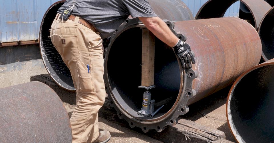
In this case, the pipe should be rounded by jacking from the inside. It is known as the Temporary Rounding Method. But before we talk about rounding pipe from the inside, let's look at few pointers as a refresher on cutting pipe in the field.
Some Quick Tips for Cutting Pipe in the Field
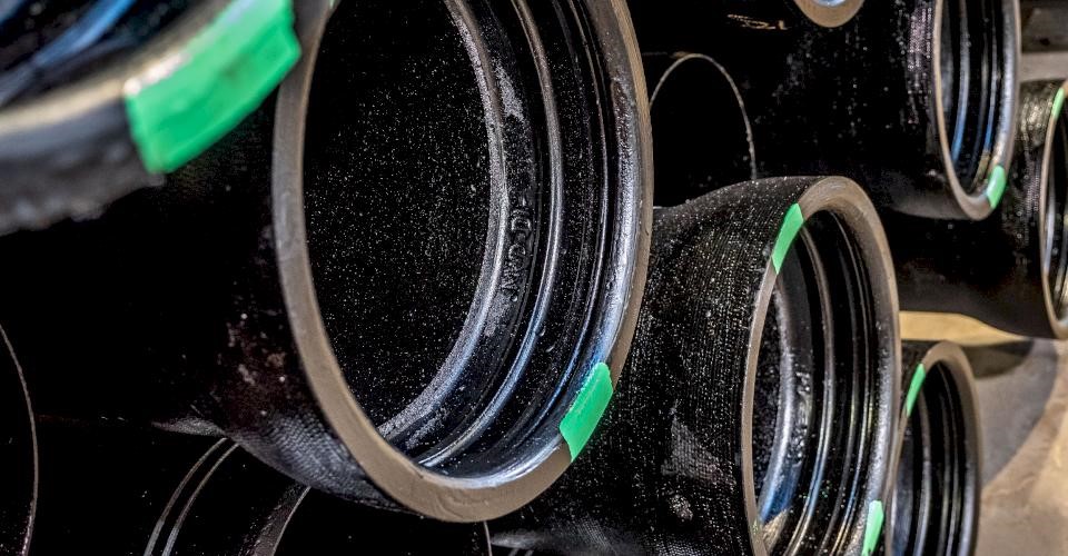
- First, for diameters 14" and larger, be sure to select a pipe that has been marked "Gauged Full Length" which can be identified by the green stripes on the face of the bell. For more information on pipe markings, check out this previous Iron Strong Blog by my colleague, Jeff Houser, where he discusses Ductile iron pipe markings and what they mean.
- Always measure the Outside Diameter (OD) of the pipe with an OD Tape prior to cutting. You can change the shape of the pipe, but you cannot change the size.
- Learn how to properly use an OD Tape with this helpful Iron Strong Blog and video by Aaron Loosli.
- Only cut pipe that measures within ANSI/AWWA C151 A21.51 Ductile Iron Pipe Centrifugally Cast standard ranges.
- To cut the pipe, use a carbide abrasive or diamond-tipped blade to make a smooth cut.
- See this Iron Strong Blog with video on How to Cut a Ductile Iron Pipe to Length by Jason Barnes.
- Bevel the spigot (if it is for a push-on joint). The outside of the cut end should be beveled about ¼ -inch at an angle of about 15 degrees. This beveling can quite easily be done with a course grinder. This technique removes any sharp, rough edges which might damage the gasket.
- To ensure the cut piece of pipe is round, a Mechanical Joint Gland can serve as a field ring to gauge the roundness of the pipe. If the gland does not fit, then the maximum and minimum diameters must be located.
- Place the short axis (minimum diameter) of the pipe vertical to prepare for rounding the pipe by jacking internally.
Suitable Pipe Diameters for Field Cuts and Restrained Joint Field Fabrication
| Nominal Pipe Size in Inches |
Min. Pipe Diameter in Inches |
Max. Pipe Diameter in Inches |
Min. Pipe Circumference in Inches |
Max. Pipe Circumference in Inches |
|---|---|---|---|---|
| 4 6 8 10 12 |
4.74 6.84 8.99 11.04 13.14 |
4.86 6.96 9.11 11.16 13.26 |
14 29/32 21 1/2 28 1/4 34 11/16 41 9/32 |
15 9/32 21 7/8 28 5/8 35 1/16 41 21/32 |
| 14 16 18 20 24 |
15.22 17.32 19.42 21.52 25.72 |
15.35 17.45 19.55 21.65 25.85 |
47 13/16 54 13/32 61 67 19/32 80 13/16 |
48 7/32 54 13/16 61 13/32 68 81 7/32 |
| 30 36 42 48 |
31.94 38.24 44.44 50.74 |
32.08 38.38 44.58 50.88 |
100 11/32 120 1/8 139 5/8 159 13/32 |
100 25/32 120 9/16 140 1/16 159 27/32 |
| 54 60 64 |
57.46 61.51 65.57 |
57.60 61.65 65.71 |
180 17/32 193 1/4 206 |
180 31/32 193 11/16 206 7/16 |
Above Table based on ANSI/AWWA C151/A21.51 guidelines for push-on joints
NOTE: The chart lists the minimum and maximum diameter and circumference. An OD tape measures the circumference. The circumference of a circle = π x the diameter. If the pipe were changed to a true oval, the OD tape would still read the same because it measures the circumference.
Click on the red arrow below to view a helpful video on rounding pipe from the inside.
Step-by-Step Instructions for Temporary Rounding Pipe from The Inside
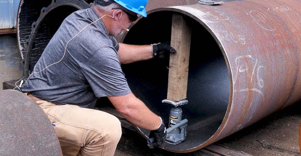
Temporary rounding by jacking from the inside is the best method for larger diameter thicker classes due to the thickness and strength of the pipe wall itself. This method increases the dimension of the short axis to make it equal to the long axis. This procedure allows oval spigots to be temporarily rounded so that assembly can be accomplished. You can usually find the tools and equipment you need to complete this project on a typical job site. McWane Ductile also offers Internal Rounding Kits.
Equipment Required for Temporary Rounding:
- Hydraulic and/or Port-a-Power Jack
- 2 Wooden Blocks (hard oak recommended) cut with a curvature to fit snugly against the contour of the pipe. 2-inch x 6-inch Ductile cut-outs could also be used.
- 2 Steel Shims (approximately 1/4-inch x 5-inch x 12-inch)
Step 1
Measure the Outside Diameter of the pipe to ensure the pipe is the correct size for installation.
Step 2
Measure the axes. Be sure to position the pipe so the minor axis (minimum diameter) is at the 12 o'clock to 6 o'clock positions.
Step 3
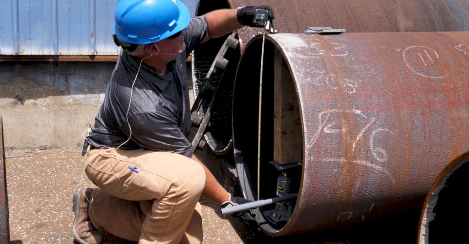
Position the shims, jack, and piece of wood. Insert the wooden blocks approximately 4 inches inside the spigot. The purpose of the wood is to distribute the load and avoid damage to the cement lining. ¼-inch steel shims are used between the jack and the wooden blocks to prevent crushing of the wood. Place the jack in line with the minimum diameter.
Step 4
Start to jack until you have tension. The jack will apply pressure to transform the oval into a circle.
Step 5
Take another axis measurement to determine if more or less tension is needed.
Step 6
Check the roundness of the pipe. A Mechanical Joint Gland can serve as a field ring to gauge the roundness of the pipe.
Step 7
Assemble the joint per manufacturer's recommendations and by following guidelines published in the ANSI/AWWA C600 Installation of Ductile Iron Mains and Their Appurtenances. Leave the jack in place during assembly.
PRO TIP: Properly lubricate gaskets. Mechanical Joints should be lubricated as well.
Step 8
Remove the jack. Check the final torque of bolts if used on a Mechanical Joint assembly.
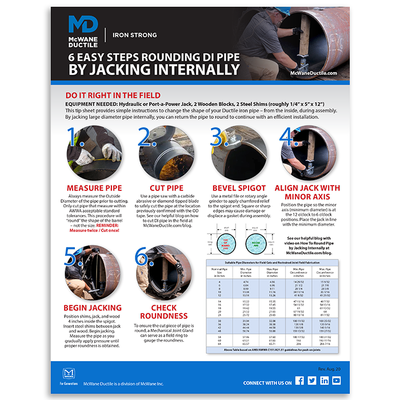
Is ovality slowing down your installation, use this handy tip sheet to quickly restore your pipe to round, and continue laying pipe!
Conclusion
On occasion, you may encounter pipe where rounding is required, especially when assembling larger diameter pipe. Luckily, and when done properly, this simple 5-minute fix can ensure you keep your pipeline installation moving with efficiency. If you have any questions about pipe rounding, or to obtain an Internal Rounding Kit, please contact your local McWane Ductile Representative.
Need Assistance with Your Waterworks Project?
We have team members who have managed small and large water utility systems, served in engineering consulting firms, and bring decades of experience in solving field issues involving pipeline construction and operation. From design to submittal, to installation, we strive to provide education assistance to water professionals throughout the water and wastewater industry.


