Cast iron pipe was introduced to the United States in 1816. Since then, numerous other piping materials have been offered and utilized. None were able to supplant cast iron as the leading performer until Ductile iron pipe became available. The introduction of Ductile iron pipe (DI pipe) to the marketplace in 1955 remains among the most significant advancements in the history of the pressure pipe industry. It was quickly recognized as a pipe material with all the established durability of gray cast iron, yet with added strength and resiliency from its innate and lasting flexibility. It was first used for special and severe conditions of high pressure, such as where water hammer and excessive external loads 1 might have existed.
Modern Ductile iron thickness classes, 50 thru 56, have been around since the mid-'70s. For each single-digit increase in the labeled thickness class, the nominal metal wall thickness requirement for DI pipe diameters of 24-inches and smaller increases by 0.03-inches. Wall thicknesses, resulting from the triad of design calculations outlined in the AWWA C150 standard, could range from 0.25-inches for a 3-inch class 51 pipe to 0.56-inches for a 24-inch class 56 DI pipe.
Ductile iron pipes from 30-inch through 48-inch diameters have wall thickness increases ranging from 0.04 to 0.08-inches per single-digit wall class bump-up, based upon the larger hoop being equally strong yet understandably more flexible than smaller diameters against external loads.
All of this allows for a custom selection of the most efficient and least-costly iron pipe available for any users' required performance scenario. These larger diameter nominal walls range from 0.43-inches for a 30-inch class 50 to 0.93-inches for a 48-inch class 56 DI pipe.
Thirty years ago, Pressure Classes (PC) were introduced for the following reasons:
- Thickness classes have no single direct meaning. They represent a grouping of similar design results from a confined range of contributive design variables upon each diameter of pipe. The three designs considered are internal pressure, barrel deflection, and barrel bending stress: the latter two being from external loading.
- Pressure Classes represent the metal wall associated directly to just the internal pressure containment rating of the pipe barrel in question, manufacturing tolerances included.
- Most other materials in the industry are classified solely by pressure rating.
- Pressure Classes can allow the customer to better tailor the pipe wall selection to certain or specific isolated job requirements. Yet, it needs to be known and understood that pressure class DI pipe is also sufficient for external loading resistance.
Please visit the Thickness Calculator within the McWane Pocket Engineer app or website at pe.mcwane.com to see how, where, and when this is true. You might just be surprised how versatile Pressure Class DI pipes truly are!
What is the internal pressure capacity limit of Class 52 DI pipe?
First, we should define Pressure Rating versus Working Pressure and Design Pressure:
- Working Pressure: It represents the average service pressure in the pipe, in service, day after day, year after year. For example – most suburban water distribution systems “work” consistently between 60 and 80-psi.
- Design Pressure: equates to the highest internal pressure anticipated through the life of the pipeline, which typically is the post-installation hydrotest pressure. Yes, it is short in duration, but the duration is not the concern. Thrust forces generated from elevated internal pressures are the issue and must be addressed via thrust blocking or the now preferred restrained joint pipe and fitting systems. There is a Pocke Engineer Calculator for that too, the Thrust Restraint Calculator!
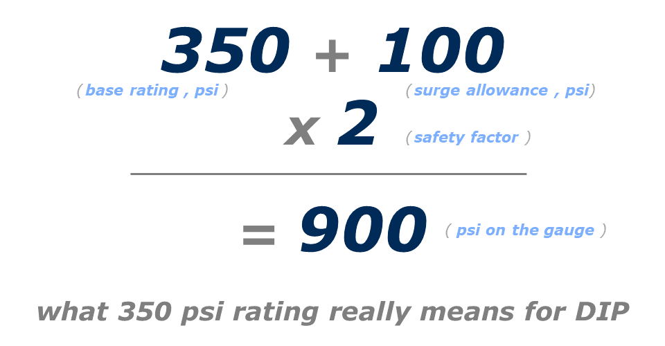
- Pressure Rating: represents the minimum valued capacity of the barrel, and in specific terms, equates to the pressure class of the barrel plus 100-psi of surge allowance, with that sum then multiplied by a safety factor of 2.0. This value, however, is NOT the ultimate pressure containment value for that DI pipe. All Thickness Class DI pipe have a pressure rating of 350-psi and, therefore, sufficient for containment of at least 900-psi water, joint restraint dependent. Manufacturing considerations that add additional metal to the required minimal pipe wall are the basis for pressure containment capabilities above the nominal wall pressure rating.
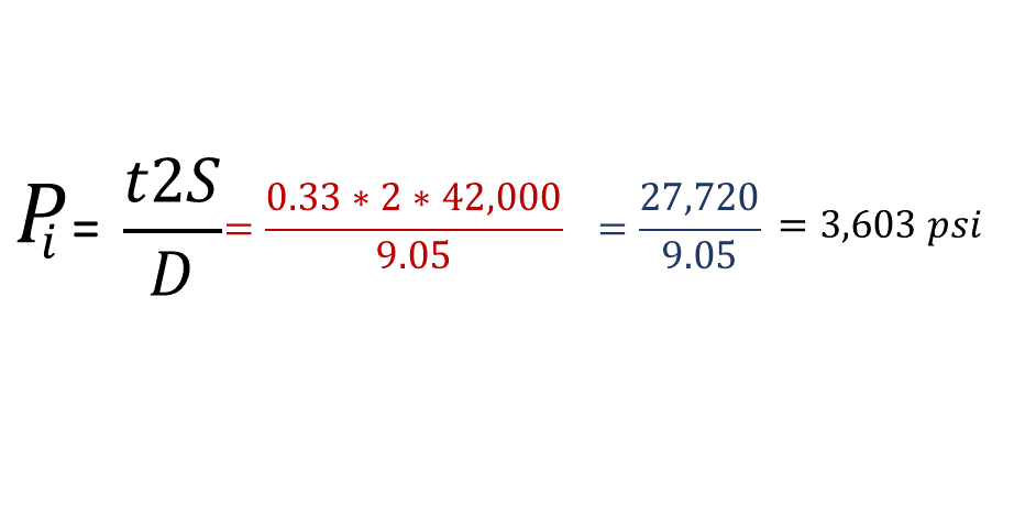
The ultimate internal pressure containment capability for a given size and known wall thickness of DI pipe can be calculated by rearranging the universal hoop stress equation.
At left is the Universal Hoop Stress equation where:
- t = computed minimum net thickness (inches)
- Pi = internal pressure (psi)
- D = nominal outside diameter of the pipe (inches)
- S = minimum yield strength for Ductile iron (42,000 psi)
Rearranging the hoop stress equation allows computation of the ultimate pressure containment capability for any given size and known wall thickness of DI pipe.
For the purposes of this article, we shall compute the maximum pressure value for 8-inch Thickness class 52 DI pipe, which has a nominal wall thickness of 0.33 inches:
If the design pressure, i.e., the highest internal pressure to be experienced, is the test pressure, typically 150-psi, the safety factor is 20!
3,063 psi / 150 psi = 20.4.
Minimal safety factors are generally set at 2.0 for most design scenarios in our industry. Yet, actual safety factors often exceed those values by a large measure, especially when Ductile iron is involved. The standardized casting tolerances and service allowances applied to as-cast metal walls of DI pipe permit these extremely impressive internal pressure handling capabilities.
In comparison, one might wonder what the ultimate pressure capability of the thinnest 8-inch DI pipe (PC 350) is? Using the nominal metal wall of 0.25-inches in the same rearrangement of the universal hoop stress equation results in an ultimate pressure containing capacity of 2,320-psi, – which equates to a performance safety factor of 15 against a hydrotest pressure of 150-psi for the “weakest” 8-inch pipe manufactured, again – restrained joint dependent to prevent longitudinal separation of the otherwise rubber-gasketed watertight joint.
Simply put, DI pipe is the strongest water main material available. Other products do not exhibit such impressive safety factors; it is not even close.
How thick does an 8-inch PVC pipe have to be to handle 2,320 psi?
Since the hoop stress equation applies to all pipe materials, we can compute the thickness of an 8-inch PVC pipe (4,000 psi material HDB strength) needed to match the “weakest” 8-inch DI pipe, a PC 350.
Plug and chug the PVC information to handle 2,320 psi results in a PVC wall requirement of 2.63-inches.
With the standardized outside diameter of 9.05 inches, this would leave an inside diameter of 3.80-inches. Talk about a substantial flow constriction! By comparison, this is less than the 4.18-inch inside diameter (ID) of a 4-inch PC 350 DI pipe!
For more on the advantages of DI over PVC pipe, check out this blog by Jerry Regula.
Introduced in 1992, for pipe size 12-inch and smaller, just one pressure class - PC 350 exists, nearly equivalent to a thickness class 50. There can be several different pressure classes in larger diameters, such as PC 150- PC 350. They are interspersed between well-established known thickness classes, as detailed in the charts below.
The charts below show the ascending order of all wall classes for each pipe diameter from 3-inches through 36-inches:
Check out the Internal Pressure and Materials Comparison Calculator within the McWane Pocket Engineer located online at pe.mcwane.com. This calculator presents several other comparative insights among the most common piping materials used today.
Every Ductile iron pipe made is individually hydrotested to a minimum of 500-psi internal pressure during the foundry inspection process in full accordance with ANSI/AWWA C151, the Manufacturing Standard for DI pipe. This is true and wonderfully demonstrative for even Pressure Class 150 pipes. And it is not a surprise because if you do the "rating math" of 150-psi design base plus a surge allowance of 100-psi and a safety factor of 2.0, you get 500-psi as the minimum rating for that “thin” pipe wall.
Conclusion
The fundamentals outlined in this article should afford you great comfort in the supreme and inherent safety factors incorporated into every Ductile iron pipe manufactured in accordance with applicable AWWA standards. Ductile iron is by far the most capable and resilient material one could choose to use in their utility systems, water, sewer, drainage, gravity flow, or pressurized.
As a convenient reminder, the easy-to-use Thickness Calculator in the McWane Pocket Engineer will calculate in a blink the governing design option (internal, deflection, or bending stress). Select the appropriate wall class for all five standardized trench types at once, and report the ultimate internal pressure containment capability for each pipe selected in the design procedure. You can't get that result anywhere else online. Get your answers today at pe.mcwane.com or download the app from the App Store or Google Play, free of charge, no strings attached! We even have a series of tutorial videos. Check 'em out.
References
- Ductile Iron Pipe Research Association, Handbook of Ductile Iron Pipe, Sixth Edition. Birmingham, AL, 1984.
- Ductile Iron Pipe Research Association, Design of Ductile Iron Pipe, Sixth Edition. Birmingham, AL, 2016.
Need Assistance with Your Waterworks Project?
If you have any questions regarding your water or wastewater infrastructure project, be sure to reach out to your local McWane Ductile representative. We have team members who've managed small and large water utility systems, served in engineering consulting firms, and bring decades of experience in solving field issues involving pipeline construction and operation. From design to submittal, to installation, we strive to provide education and assistance to water professionals throughout the water and wastewater industry.

