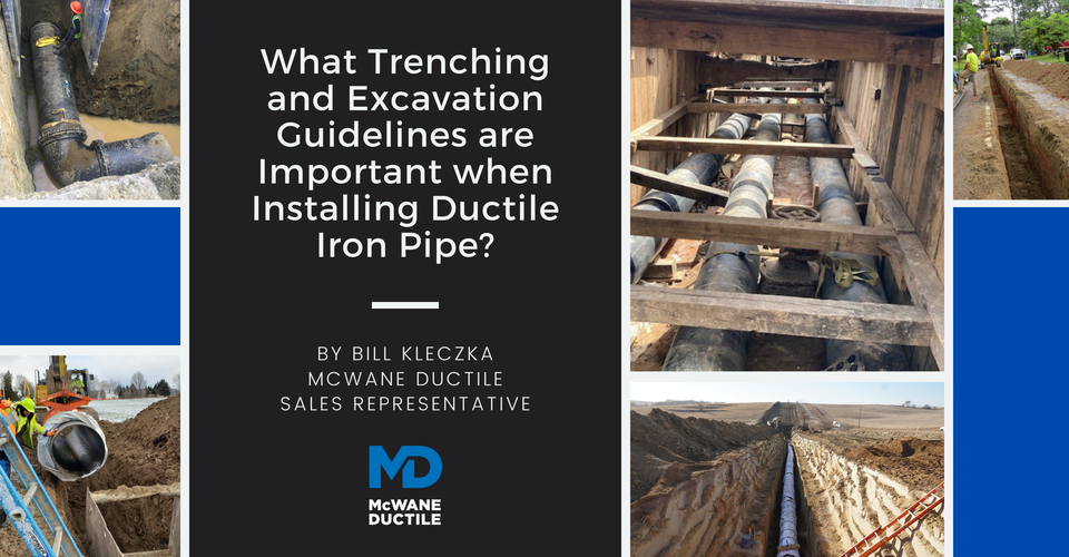
Have you ever been asked what size trench is needed when installing Ductile iron pipe (DI pipe)? How safe are the working conditions within a trench? Knowing the proper trench to utilize during the installation of the material will help save time, effort, and money on any job site. But most importantly, this knowledge will help keep everyone safe within and around the trench. The Occupational Health and Safety Administration (OSHA) has gone to great lengths to define and identify any threats in the trenching and excavation safety when installing DI pipe. This Iron Strong Blog will share and explain the different trenches available while outlining the safety considerations required when excavating earthen material.
The Trench Safety and Excavation Considerations
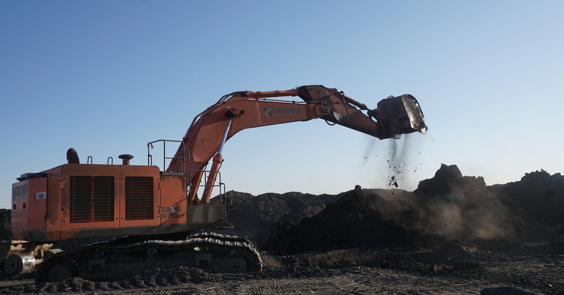
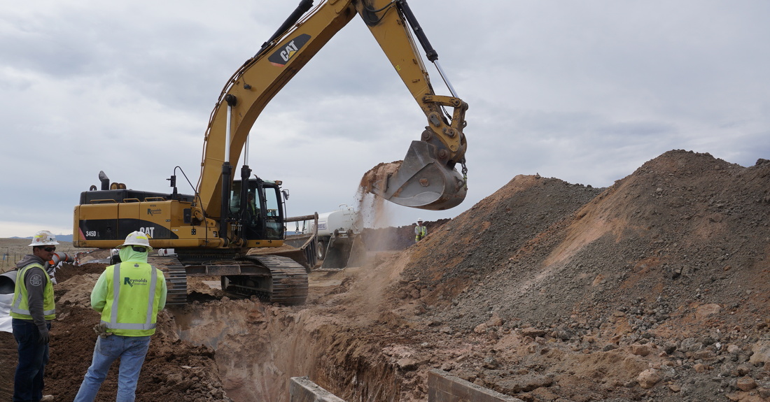
When it comes to digging any trench, proper pre-construction planning is necessary to ensure the installation's safety. Utility locates must be done before any digging or excavation has started. This step is an essential function within OSHA jurisdiction and a primary reason why these trenching standards are in place; to ensure the workers' safety and prevent cave-ins within the trench.
Trench wall collapses can lead to anything from loss of time on a project to the worst-case scenario of loss of life. The best way to protect against these potential hazards is to ensure that all proper protective gear is engaged and in place before entering any underground construction site.
Two of the most dangerous things on a construction site are the trenches and excavation areas. OSHA has integrated a comprehensive system of regulations helping outline the safety of construction workers while taking into account the factors associated with an excavated trench. Together we all can ensure the safety of everyone involved while observing the guidelines required when installing Ductile iron pipe.
Trench protection is essential for any commercial trench with depths of five feet or greater. Trenches with depths of 20 feet must have a system of safety designed by a registered engineer or have the calculated data of this trench approved by a professional in this field. The different types of trench protection systems are below.
- Shoring – The most common system of protection when installing Ductile iron pipe in urbanized or built-out areas i.e., streets, pavement. Shoring is the act of installing supports in the trench to prevent soil shifting and cave-ins.
- Shielding – The use of trench boxes or similar walls in the trench to avoid soil cave-ins. The stacking of these shields or trench boxes is common as trench depths become deeper.
- Sloping – A protection method of trench safety when space around the trench is plentiful. Sloping is defined as the cutting back of the trench wall an angle away from the excavation trench.
- Benching – The process of excavating the earth from the sides of the trench to create horizontal steps or benches. This protection method can only be used with specific soil types.
The Trench Bottom
The key to a good trench bottom is a firm, unyielding subgrade in the trench. Having this will unlock a smooth installation across your project. Adding rock, sand, or stone in small 2-inch to 3-inch lifts will also help keep the trench bottom stable while maintaining grade. Compacting this aggregate in the trench is recommended to help achieve a sound installation.
Bell Holes should also be used at each joint to facilitate assembly and provide the space for proper overlaps for any polyethylene encasement if required over the Ductile iron. These bells holes only require a minimal depressed area big enough to assemble the joint correctly. A guide for trench width is the nominal pipe diameter plus 24 inches. A further consideration for trench width should also include any appurtenances to be installed.
The Soil and Types of Trenches
There are five standard trenches based on the laying conditions and soil being excavated. The engineer or utility of record should call out these trench types in the project specification.
As a reminder, trench type specifications vary from one project to another and may also vary from one section of a project to another. These five types of trenches are described and shown in ANSI/AWWA C150/A21.50 and ANSI/AWWA C600.
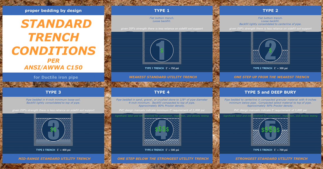
- Type 1 Trench – Undisturbed earthen trench with loose backfill.
- Type 2 Trench – Flat bottomed trench consisting of lightweight backfill up to the spring line of the pipe.
- Type 3 Trench – Trench where pipe is bedded in a minimum of 4 inches of loose soil. The backfill is consolidated lightly up to the top of the pipe.
- Type 4 Trench – Trench where the pipe is bedded in the crushed aggregate, sand, or gravel to a depth of an eighth of the pipe diameter utilizing 4 inches minimum backfill compacted to top of pipe. Compaction to be approximately 80 percent Standard Proctor.
- Type 5 Trench – Trench with a pipe bedded to its centerline in compacted granular material, a 4-inch minimum under the pipe with compacted granular or select material to the top of the pipe. Compacted Granular material is limited in size to a 2-inch maximum per the ANSI/AWWA C600 Standard. Compaction to be approximately 90 percent Standard Proctor.
Compaction Further Explained
Standard Proctor is a scale developed in 1933 by Ralph R. Proctor of the University of California. The scale is used to achieve controlled compaction of the soil in the field. The Standard Proctor Test determines the optimum moisture content at the maximum dry density. (Source: 9 to 5 civil) Soil compaction testing is also outlined in the AASHTO T-99 Standard (American Association of State Highway and Transportation), which defines the specific method and test equipment used to determine the level of compaction/density.
Objectives of the test:
- To investigate the moisture density relationship of soil.
- To determine the compaction characteristics of soil under variable moisture content.
- To determine the optimum moisture content that will result in the maximum soil unit weight when compacted with a particular effort.
Compaction methods used are vibrating, rolling, or tamping.
Results of proper compaction include:
- Enhancement of the soil’s engineering properties pertinent to load-bearing.
- Reduces the probability of soil settlement – especially important in the event a structure is constructed over the soil.
- Increases the stability of the slopes of embankments.
- Augments the shear strength of soil by enhancing its frictional properties.
- Reduces the permeability of the soil.
The Proper Trench Excavation
Before any pipe is installed and put into service, the area or the trench must be prepared safely. In almost all instances or regions of the nation, Ductile iron must be installed with a specific minimum cover over the pipe. Whether it be because of surface load or a frozen line, the minimum cover designed and required is to protect and create the maximum service life of the Ductile iron. No matter where you install Ductile iron pipe, each and every jurisdiction has standards that must be followed when excavating a trench.
Trench width depends on the diameter of the pipe. It needs to be wide enough to assemble the joints correctly while allowing enough space to safely move and allow enough space to tamper and compact when backfilling. When determining the trench's width, you must consider the soil type, the depth of the install, and the equipment being used to dig it. The table below outlines the suggested trench width (inches) based on the installed pipe diameter.
| Nominal Pipe Size (inches) | Trench Width (inches) | Nominal Pipe Size (inches) | Trench Width (inches) |
| 3 | 27 | 20 | 44 |
| 4 | 28 | 24 | 48 |
| 6 | 30 | 30 | 54 |
| 8 | 32 | 36 | 60 |
| 10 | 34 | 42 | 66 |
| 12 | 36 | 48 | 72 |
| 14 | 38 | 54 | 78 |
| 16 | 40 | 60 | 84 |
| 18 | 42 | 64 | 88 |
Extreme Conditions
What if an "oh-my moment" occurs. That moment when conditions will not permit standard trench installation. The true soil conditions may have been underestimated during design or may have changed. A change in direction may avoid the area of concern but may add material and labor costs to the project.
Another option may be to place the new line on piers, which will most likely increase the project's cost. Horizontal Directional Drilling (HDD) has been a proven installation method for decades. One would think this application is generally more expensive than standard open trench installation. However, the overall cost of installation may be reduced using the HDD process when all factors of the installation methods are considered.
Summary
Proper trenching and excavation are not simply digging a hole and dropping in a new line. Specific guidelines are available tools given to ensure the project is properly completed safely, and with long-lasting results. The keys to success are communicating this information to all affected parties associated with the project and proper execution of procedures that will improve the final product.
For more information on this topic, see these Iron Strong Blogs by my colleagues:
Need Assistance with Your Waterworks Project?
If you have any questions regarding your water or wastewater infrastructure project, be sure to reach out to your local McWane Ductile representative. We have team members who've managed small and large water utility systems, served in engineering consulting firms, and bring decades of experience in solving field issues involving pipeline construction and operation. From design to submittal, to installation, we strive to provide education and assistance to water professionals throughout the water and wastewater industry.

