What does balancing a checkbook and restraining Ductile iron pipe (DI pipe) have in common? They are both important skill sets that lead to peace of mind. A typical waterline experiences thrust forces produced by fittings, closed valves, or dead ends. These forces must be "balanced out” or canceled to maintain the pipeline’s longitudinal integrity across the joints. Similar to managing a checkbook, the weight of the pipe, the water contained in it, and the backfill above it, along with the pipeline's friction with surrounding soils, help counteract a portion of the "thrust force" bill. The remaining force must be zeroed out using a calculated length of restrained joint pipe and fittings, following the ASTM/AWWA calculation protocols.
In this Iron Strong Blog, we will explain thrust forces, how they are created in a water line, why they are important, the information needed to calculate them, and how to easily calculate them using the McWane Pocket Engineer™. Once you have those calculations, we will show you what pipe joints to use and in what quantities to make your pipeline restraint secure for generations.
What are thrust forces, and how are they created in a waterline?
Thrust is the force that propels an object forward, like the engines on an airplane. It occurs when matter is forcibly accelerated in a specified direction. Regarding pipelines, thrust forces are unbalanced forces that can occur due to the pipelines’ geometry. These forces can happen at any point in a pipeline where the direction of its contained fluid changes. For instance, at any tee, bend, or dead end (such as a closed valve).
Yes, fluid movement that is forced to come to a stop constitutes a directional change. In fact, a dead end or closed inline valve is the most significant generator of thrust force, followed in descending order by:
- a 90° bend,
- a 45° bend
- a 22.5° bend
- an 11.25° bend
In comparison, inline sleeves do not create any thrust but can pose a risk to thrust forces if there is a gap within an unrestrained sleeve in the pipeline.
Explaining "L" ...also known as the "Wiggle Zone"
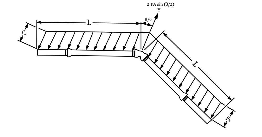
Dimension ‘L’ in the diagram above represents the Length of the pipeline prone to “wiggling” and potential joint separation due to thrust forces generated by fluid movements inside. All joints in the “wiggle zone” (L) must be longitudinally restrained, including both sides of the fitting. For instance, if L = 190 feet, then the number of joints within would be 190÷18 = 10.6 or rounded to 11 pieces. If the bell or spigot of any pipe is involved in a restrained joint, that entire piece of pipe is effectively restrained in place. The Thrust Restraint Calculator in the McWane Pocket Engineer™ quickly and easily computes these lengths for you under any conditions you prescribe.
Why is it essential to account for thrust force?
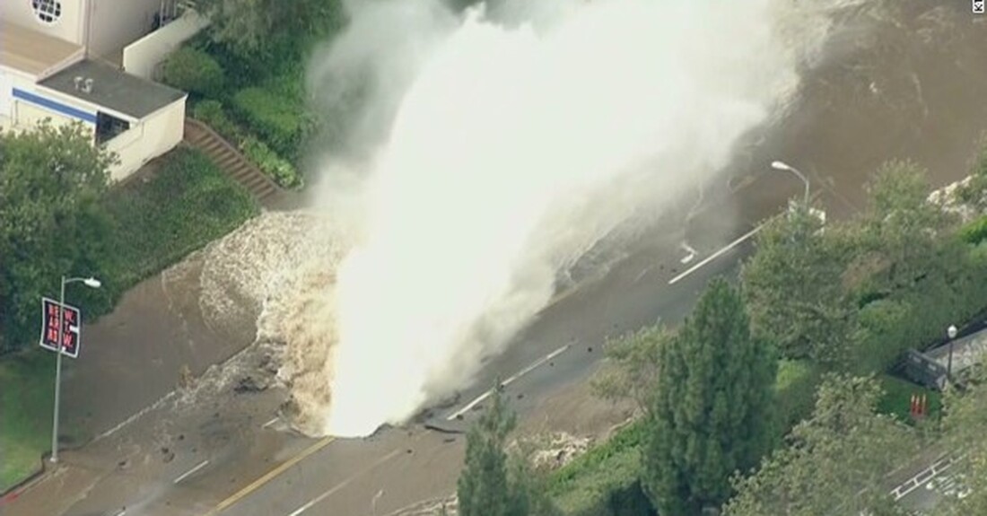
If thrust forces are not adequately accounted for, the pipeline could have significant problems and joint separations. The location of the potential separation could also be critical. For instance, imagine a pipeline correctly installed in the heart of your hometown, but the thrust was miscalculated. When the pipeline is filled, there’s suddenly an unwelcome swimming pool in the city’s highest traffic area. The costs and effects of water or sewage in unwanted places don't end with its initial appearance, not by a long shot! Every gallon spilled must go somewhere, and cars, buildings, or basements are at the top of the list of worst-case scenarios. This is one example of why properly accounting for thrust forces is essential.
What information will you need to calculate thrust force?
The distance to restrain for each fitting or valve in the pipeline is a function of numerous factors, such as:
- Soil conditions — Soils that offer more frictional resistance require less restrained joints to contain an equal force in less resistant soil. Sand grips pipe more than clay, although clay may weigh more.
- Type of pipe and its diameter — PVC pipe will require more footage of restraint due to its smooth exterior surface. Pipe diameter also affects the number of restrained joints needed. The more surface area there is, the more soil friction there will be to hold the pipe in place.
- Depth of cover affects the amount of restraint needed by changing not only the weight directly upon the pipe but also assists in the development of trench friction.
- Design pressure — The higher the internal pressure, the greater the thrust force generated. IT IS INCREDIBLY IMPORTANT TO USE THE HYDROSTATIC TEST PRESSURE that will be applied post-installation in the field to the pipeline as the THRUST RESTRAINT DESIGN PRESSURE.
- Trench type — The stiffer the trench, the greater the grip on the pipe. A Type 1 trench grips far less than a Type 5 trench.
- Type of directional change- bend, tee, dead end, valve, etc. — as mentioned earlier, the sharper the turn, the greater the thrust force developed. Think motorcycle or roller coaster on a tight curve vs. a shallow one.
- Vertical or horizontal installation — vertical fluid movement through bends creates more thrust than in a horizontal alignment.
- Polyethylene Encasement — is protective yet somewhat slippery against most soils. Such encasement, critical for corrosion control of many pipelines, can increase the required restraint lengths by nearly 30% in some cases.
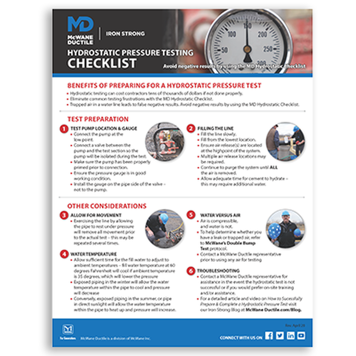
With this free Hydrostatic Pressure Test Preparation Checklist from McWane Ductile, you can avoid negative test results and succeed the first time!
How do we use the McWane Pocket Engineer™ to accommodate thrust forces?
McWane Ductile provides the McWane Pocket Engineer™, which serves various design requirements, such as the Thrust Restraint Calculator. This calculator considers all relevant contributing factors. You can access the calculator for free at pe.mcwane.com or by downloading the app from the Apple Store or Google Play for use on your phone.
As an example, a 12-inch Ductile iron pipe, 3 feet of cover in a Type 1 Trench with a design pressure of 250 psi in medium silt soil, and a 12-inch, 45-degree bend would need to be restrained for a minimum of 56 feet on both sides of the bend (horizontal or vertical up alignment) to avoid pipe joint separation due to the fitting being present thus generating thrust forces. If aligned vertically, the restraint requirement increases to 120 feet against these conditions.
One nice feature of this calculator is that, for a single simple input scenario, it computes results for every type of bend or other common fitting available in the selected diameter, such as tees or reducers. Also, the user can easily change any default values, such as soil density (weight in lbs/cf), to match your designs. In an effort for responsible consistency, the McWane Pocket Engineer default Safety Factor of 1.5 is the standard selection for similar online thrust restraint calculators.

What pipe can be used to ensure the thrust forces are accounted for?
Types of restrained joint systems have evolved from concrete thrust blocks and external bolted bell restraints to more efficient restrained pipe joints, such as the TR Flex® Joint, and restrained joint gaskets like McWane Ductile’s Sure Stop 350® Gasket.
Restrained joint gaskets, sometimes called “gripper gaskets," consist of a standard Tyton® (push joint) gasket but have embedded “teeth-like” stainless steel segments that bite into the exterior surface of the pipe spigot for a secure connection. However, due to potential vibration concerns, these gaskets are not recommended for specific above-ground applications like bridge crossings.
The TR Flex restrained joint utilizes the Tyton joint gasket for a watertight seal, a factory-adapted spigot, and extended bell casting to provide positive and permanent joint restraint. Locking segments are placed within the extended bell portion to complete the installation after the standard Tyton joint is belled up. The locking segments are self-explanatory as each set consists of a “Left Hand” (black) and “Right Hand” (red) segment along with a rubber retainer. See this Iron Strong Blog for more details: What is TR Flex Pipe, and How is it Assembled?
TR Flex is the easiest manufactured restrained joint to install or disassemble. Because the locking segments are not integrated into the gasket, separating a joint is as easy as removing each segment and then pulling the pipe apart. Mechanical Joint fittings with wedge-action retainer glands, commonly called "meg-a-lugs," are often utilized with TR Flex pipe or similar restrained joint pipes.
If desired, TR Flex fittings can be used with TR Flex pipe for a completely boltless restraint system. This system is ideal for numerous applications, such as traditional open trench projects and Horizontal Directional Drilling, and is widely used for pipe on piers (aerial) or bridge crossings.
When utilizing the TR Flex Joint, it is recommended that you manually pull the slack out of the joint once it is assembled. The pipe is designed to breathe and flex, resulting in a small amount of room between the fully inserted spigot and the contact point between the metal wedges and the weld bead at the pipe's spigot end.
If the slack is not removed, there is a risk of the pipe “snaking” when internal water pressure is applied. This is especially important when utilizing TR Flex pipe for aerial installations such as bridges or pier crossings. The snaking is mostly a visual concern; the joint is designed to withstand such occurrences. It can happen to buried pipelines as well; you just don’t see it.
One of the two advantages of utilizing TR Flex or Sure Stop 350 Gaskets versus an over-the-bell harness method is that they go together much faster. The harness assembly is a time-consuming process in and of itself. Secondly, the pipe deflection is removed, essentially tying each restrained piece into a straight line. TR Flex and Sure Stop 350 Gaskets provide the ability to deflect the pipe during installation while retaining the ability to resist pulling apart.
Why Not Use Thrust Blocks?
Let's discuss some issues that can arise when using concrete thrust blocks. Essentially, a thrust block is only as good as the soil supporting it. If you do not adequately address the soil surrounding the concrete, the thrust will push the concrete into the soil, which could lead to failure. Thrust blocks are often challenging to pour per the engineer's specific design, which leads to ineffective restraint.
Keep the following in mind: Space may be limited in a densely populated metro area, and many concrete thrust blocks can be the size of a car or larger. Future excavations for new utility lines or other construction activities can affect these thrust blocks. When pouring concrete behind mechanical joint connections, there is a risk that the weight of the thrust block may damage the connections. This may cause the thrust block to rotate as the soil settles, leading to failure.
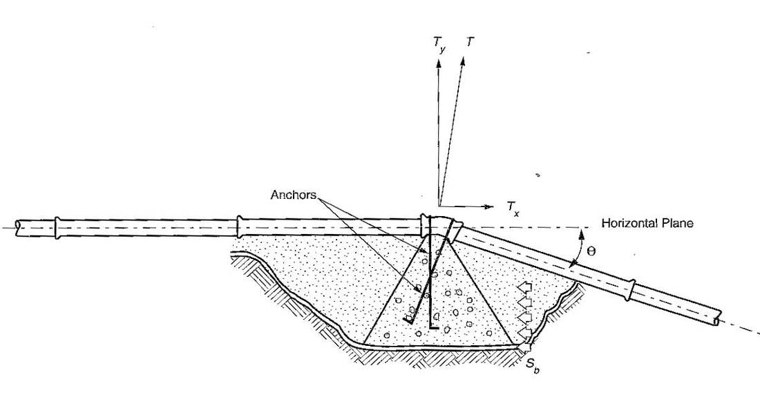
So, what about using a restrained joint pipe with a thrust block? This is referred to as the "belt and suspenders” approach. It is NOT recommended to use this combination method for any installation. While this method could ensure that the thrust block is protected against future excavation or soil changes, it often results in the installer performing one or the other half-heartedly.
Municipalities, utilities, and contractors’ preferences may vary, but the bottom line is that restrained joint systems are meant to keep the pipeline intact and operational. Hopefully, this blog clarified the concept of thrust forces, why they are significant, and how to effectively counterbalance these forces in your pipelines. If not, contact us for more information or design application assistance. Our Sales Operations and Engineering group is available to help.
No one wants to receive a "bounced check" or "overdraft" notice from their bank, just as no contractor or neighborhood wants "bubbling pools of water" or "unintended sprinklers" from their pipelines! Proper design of restrained joint needs can prevent costly mistakes. Using the free McWane Pocket Engineer to guide your designs can greatly aid in the fiscal and physical success of your pipelines!
Need Assistance with Your Waterworks Project?
If you have any questions regarding your water or wastewater infrastructure project, your local McWane Ductile representative is equipped with the expertise to assist you. Many of our team members have managed small and large water utility systems, served in engineering consulting firms, and bring decades of experience solving field issues involving pipeline construction and operation. From design to submittal to installation, we strive to educate and assist water professionals throughout the water and wastewater industry.
