What is Ball & Socket Pipe?
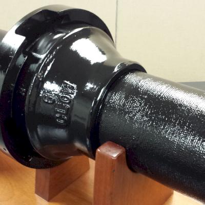
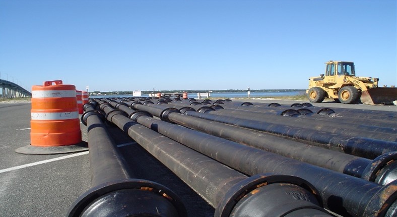
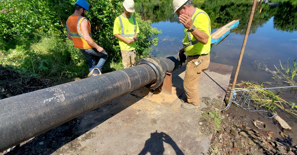
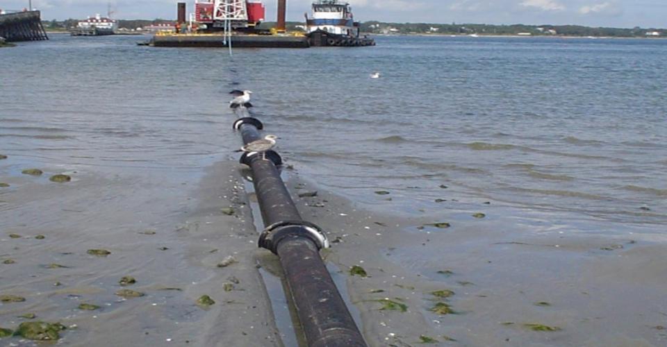
As the name suggests, Ball & Socket River Crossing Pipe manufactured by McWane Ductile is a severe application Ductile iron pipe (DI pipe) product manufactured to meet the demanding requirements associated with crossing rivers, streams, and lakes. In this blog, we will discuss the various installation methods associated with Ball & Socket pipe and basic assembly instructions.
Ball & Socket pipe utilizes a push-on boltless fully restrained joint pipe with the ability to freely deflect a full 15 degrees in any direction without the obstruction of the waterway. Deflection of 50 to 80 percent of the stated degree of deflection per pipe size should be utilized for design purposes. Required permitting is frequently required to cross a waterway. Requirements vary depending on location. Check with local authorities during the design of such a project.
One option to reduce environmental impact is installing the pipeline through the Horizontal Drilling Process using TR Flex® pipe. This process will reduce the need for permitting requirements which can be costly and may take a considerable amount of time for approval.
Restraint joints such as the TR Flex joint are limited to a maximum of 5 degrees of deflection per joint compared to the 15 degrees obtained using the River Crossing pipe. The designer has the option to use either type or possibly a combination of both joints, optimizing the efficiency of the system.
How is the Design of Ball & Socket Pipe Different than Other Ductile Iron Pipe?
Ball & Socket Pipe is manufactured to exacting quality, weight, and dimensional standards. Manufactured and tested to ANSI AWWA C150 Ductile Iron Pipe Centrifugally Cast, the components are cast to a 70-50-5 grade of iron and machined to precise dimensions. The pipe and components are tested both as individual parts as well as individual units.
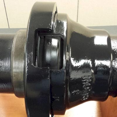
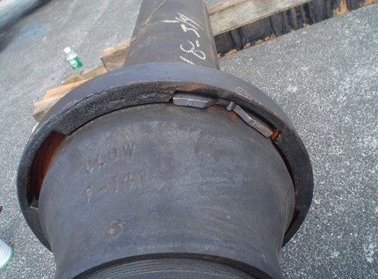
The pipe joint is boltless, consisting of a bayonet-style lock of the retainer ring over the bell. The joint, once fully assembled, is completed with the use of a retainer lock and pin to prevent the retainer ring from rotating and possibly disengaging after assembly
Pipe is supplied with symmetrical-shaped, non-directional gaskets, which aid in easy installation and prevent the gasket from being installed incorrectly.
Ball & Socket Pipe can be manufactured in several end configurations, including:
- Ball and Plain End, or Bell and Plain End
- Ball and Push-On Restrained Plain End, or Bell and Push-On Restrained Plain End
- Ball and Push-On Restrained Bell, or Bell and Push-On Restrained Bell
Pipe design includes a rather conservative working pressure rating of:
- 350 psi for sizes 6” thru 24”
- 250 psi rated for sizes 30” and 36”
Common Assembly Methods Include:
Assembly Line Method
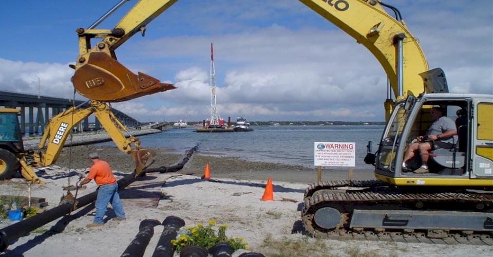
Ball & Socket Pipe is assembled in a staging area prior to installation. Complete or sections of main are positioned into place.
Cartridge Style Method
This option is often used when space is limited in the staging area. Pipe is assembled one pipe at a time, then advanced into the water crossing.
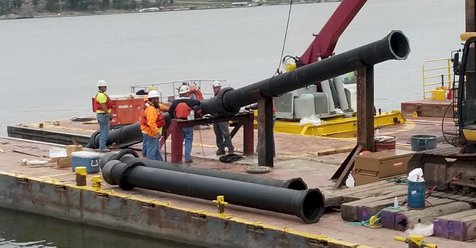
Barge Installation
Installation from a barge must include a chute to support the pipe from over deflection when lowered from the barge.
Floated and Sunk
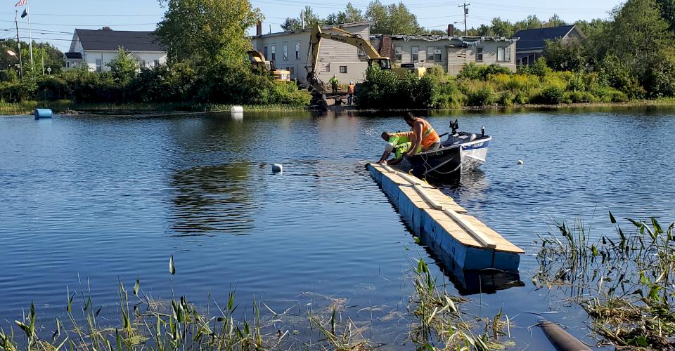
With this method, the pipe is capped and floated across the waterway. It is then sunk into position while full of air. The flotation/buoyancy is based on the size/class of the pipe.
The pipe is then pulled into position by barge/machine. The waterway may require dredging prior to installation to create a uniform base. I encourage you to read another Iron Strong Blog by my colleague, Ken Rickvalsky, where he details a river crossing project in Milo, Maine that utilized the float and sink method.
Crane-Mounted Barge Pull/Machine Push
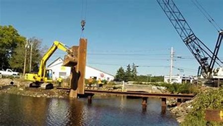
Cofferdamm
A cofferdam creates a temporary barrier in or around a body of water that allows de-watering, diversion, or damming of water within an enclosed area. The primary purpose of any cofferdam type is to hold back overwhelming or inconvenient waters and create a dry work environment while installing pipe below the waterway bottom.
How is the Ball and Socket River Crossing Joint Assembled?
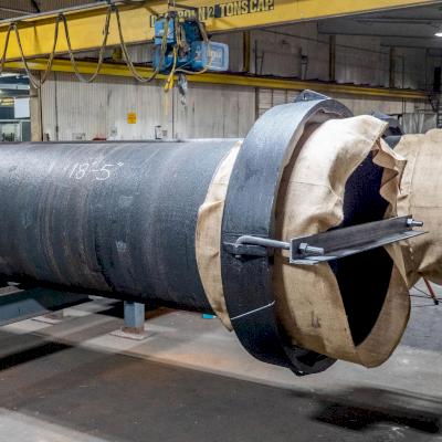
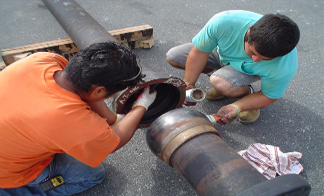
1) Remove protective accessories (hook holts and burlap) from the retainer- (attached to prevent damage during shipping).
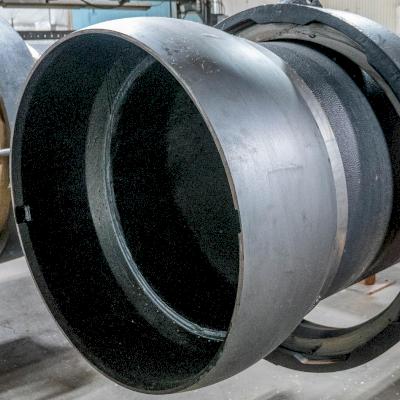
2) Thoroughly clean the machined ball and bell area (mineral spirits) to remove the protective layer. A hand wire brush or mechanical brush may also be used to ensure the cleanliness of the machined components.
3) Remove all debris that may have entered the gasket seat area of the bell and apply NO-OX-ID® lubricant.
4) Properly insert the gasket by use of loop (heart shape) seat bottom half of gasket, then push remaining loop into the top portion of bell. Be certain the gasket is seated correctly in bell recess with no part of the gasket protruding above the recess. Large-diameter pipe may require additional loops in the gasket during installation:
- 6-18 inches—one loop
- 20-24 inches—two loops
- 30-36 inches—three loops
5) Clean the area at the ball end of the pipe (neck) to be sure this area is free of dirt/debris that would affect the free rotation of the retainer ring during final installation.
PRO TIP: Use a wire brush on the surface to ensure all rust preventative is removed from the surface of the bell and ball.
6) Once the ball and bell are positioned in close proximity, Push-On Joint assembly is accomplished by first lubricating the gasket face and ball. Ensure straight alignment with the ball and receiving bell, and force the ball completely home inside the bell using a come-along winch or available machine.
7) Position retainer over receiving bell, (be sure the roll pin hole is accessible), and with a ¼ turn in gauge, the joint retainer with the bell lugs.
8) The final step is to insert the retainer lock and stainless-steel roll pin to prevent lug rotation during the final positioning of the pipe. Only after the joint is fully assembled can joint deflection be considered
9) Care should be taken to support the assembled Ball & Socket River Crossing Joint Pipe during transportation and installation to prevent the weight of the pipe to over deflect (beyond 15 degrees). A lack of support can cause damage to the joint assembly. A strong back may be used to prevent over-deflection of the joints when multiple connected pieces of pipe are lifted at one time.
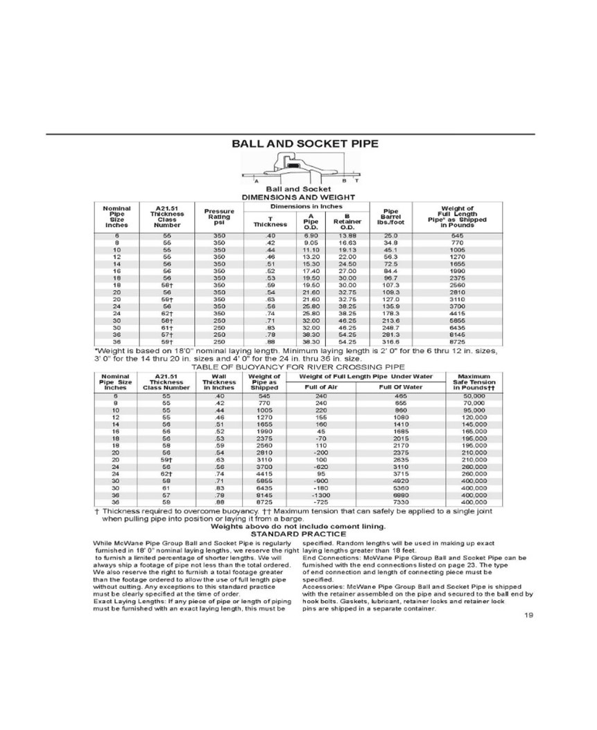
You can find additional reference concerning Ball & Socket Joint pipe sizes, weights, and dimensions, including thickness to overcome buoyance and safe-end pull tension, in the following chart:
Is Polyethylene Required for Corrosion Control?
Polyethylene encasement is typically not required for subaqueous installations when the pipe is to be totally submerged in fresh and saltwater. Consideration should be given for locations where the water ebbs and flows or during the transition from submerged to dry areas. The area of transition is also a location where a combination of restraint piping in addition to the River Crossing pipe is recommended.
Further Methods of Corrosion Control
Additional corrosion control methods such as bonding the joints for cathodic protection or adding a sacrificial anode system to the pipe are generally not utilized. Systems of this nature would require bonded coatings that are typically not recommended for use with DI pipe.
Furthermore, the joints would, in turn, need to be wrapped, which may reduce the flexibility/deflection of the River Crossing joints. Again, studies have indicated that Ductile iron pipe is typically not affected by fresh and saltwater when the pipe is totally submerged. A corrosion study regarding the specific project is highly recommended before considering any advanced cathodic protection system.
Crossing a river, lake, or bay? Assemble your Ball & Socket Joint Pipe correctly with these free, helpful instructions from McWane Ductile!
Summary
The information provided in this article should stand as a solid reference of some of the common Ball & Socket crossings experienced by McWane Ductile. Although each project was unique and had its own level of difficulty, these projects require a great deal of advanced planning. As each site is different, the approach to the crossing should also be different. Sound engineering practices should be employed to make a safe and successful crossing. Items such as deflection limits, safe end pull strength, and buoyance of the pipe are just a few factors to consider when developing a strategy to accomplish this type of crossing.
Please consult your local McWane Ductile Sales Representative for assistance in designing, specifying, and installing the appropriate Ductile iron system to meet the specific requirements of your project. Our Engineering/Technical Support Groups also stand ready to aid in utilizing specialty products from project conception, product selection, and submittal through installation and testing. We welcome you to reach out to discuss your project needs and your unique situation further.
For additional information on River Crossings use the following link to the Ductile Iron Pipe Research Association publication Ductile Iron Pipe Subaqueous Crossings at https://www.dipra.org/ductile-iron-pipe-resources/technical-publications/applications
