Engineers are busy. They are faced with making crucial calculations every day, especially regarding water and sewer infrastructure. This article will discuss five ways to properly select the wall thickness of Ductile iron pipe (DI pipe).
Each of these ways are performed in strict accordance with the latest edition of ANSI/AWWA C150, the Thickness Design Standard for Ductile Iron Pipe. Three of these ways are quick and easy, the other two ... not so much. The method you employ can be dictated by the level of accuracy you seek in the result. None will give you a wrong answer, but one can give you the best solution, i.e., the one most properly fit to your design conditions.
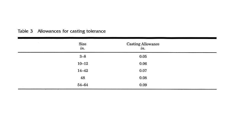
The AWWA C150 Design Standard invokes a detailed three-prong approach that examines independent results for Internal Pressure containment and the Ductile iron walls required to resist failure against Bending Stress and Deflection Design limits from external loading. The worst of these three (3) calculations, the one requiring the thickest wall, is considered the governing design, to which casting tolerances and service allowances are then added to determine the minimum manufactured wall thickness you should use for your design circumstances.
The design of most other alternate materials today stops at Internal Pressure requirements, thereby presuming the trench will handle all external loads. Which, simply put, means you are too often paying FAR TOO MUCH for a COMPACTED TRENCH that you typically do not need with DI pipe.
So, let's start there. What thickness is required to contain a given pressure? For all pipe materials, this is computed using the universal hoop stress equation:
Where: t = Pipe wall thickness, inches
Pi = internal design pressure, psi = 2 (Pw +Ps)
Pw = working pressure, psi
Ps = surge allowance = 100 psi, based on 2.0 fps change in flow velocity in Di pipe
D = outside diameter of pipe, inches
S = minimum yield strength in tension, 42,000 psi for Ductile iron
Plug & chug this equation for an 8-inch DI pipe with a 150-psi working pressure involved, results in a net thickness (t) of just 0.05 inches. That's just less thickness than 12 sheets of 20-lb. economy printer paper (3.8 mils each) stacked on top of each other, and certainly, such a thin hoop will not stay round, even given its strength when made of iron. Fortunately, the conservative nature of DI pipe design adds a Casting Tolerance and Service Allowance to this computed minimum net thickness, which in this case results in a needed manufactured thickness of 0.20 inches. The first 8-inch pipe to offer this 0.20 wall thickness is a PC 350 with a 0.25-inch nominal wall.
Rearranging the hoop stress equation to compute directly for the maximum pressure this 0.25-inch PC 350 DI pipe wall can handle (as shown below) equates to 2,320 psi. Laboratory testing has proven such values for DI pipe to be true.
Given the universal hoop stress equation's applicability to all piping materials, we can compute the maximum pressure that a PVC pipe (4,000 psi material HDB strength) with a 0.25-inch wall could handle would be 221 psi, which does not include a surge allowance (given the rearranged equation above). Any surge consideration must be subtracted from this computed value. Hoop stress is a SMALL equation that can point out BIG differences among materials.
For more on the advantages of DI over PVC pipe, check out this Iron Strong Blog by Jerry Regula.
Interested in a Lunch & Learn comparing the various pipeline materials when designing a pipeline? See this link to arrange your webinar with McWane Ductile.
Here Are Five Ways to Properly Design / Select a Pipe Wall
By finding the thickness to independently resist Bending Stress & Deflection Limits
1. Doing the Actual Math - aka The Long Way
The governing thickness of DI pipe is determined by considering the trench load and internal pressure separately.
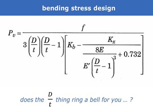
Bending Stress is the force at which the pipe would fail via crushing by the combined external load of soil and traffic (live loads). Deflection Design considers a one-time and/or repeated load upon the pipe that does not fail it but briefly reshapes the barrel to a prescribed limit of its original diameter not to fail any internal lining.
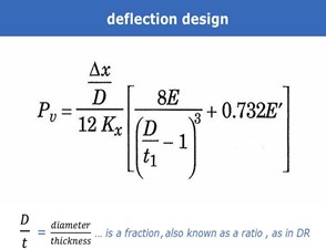
The limit recommended by AWWA C150 is 3.0% for cement mortar linings and 5.0% for more flexible linings such as ceramic enhanced epoxies. DI pipe's wonderful advantage is that it is not weakened over time by cyclic pressures, whether they originate from within or eternally. For more detail on Cyclic Pressures, please see another helpful blog from my colleague Ken Rickvalsky, a McWane Ductile Product Engineer.
The net thickness (t) cannot be solved directly in these equations as it is buried in the bottom of a fraction within the denominator on the wrong side of the equal sign. This makes both designs an iterative process. In other words, "guess" at a D/t and D/t1 value, do the math with other known values involved, see if your result exceeds the known total trench load (Pv). If it does not, use a slightly higher or lower presumed D/t value until your result meets or slightly exceeds the known Pv value. Hence the somewhat hideous nature of this repeated "plug & chug ... & chug" design.
The fractions seen here as D/t and D/t1 are numerical expressions of the pipe's diameter related to its wall thickness. For example, a theoretical 50-inch pipe with a 1-inch thick wall would have a dimension ratio (DR) of 50. Give it a 2-inch thick wall, and the DR becomes 25.
You can see from the equations and process above why few, if any, would favor doing these calculations by hand, especially given other calculation options available today, but just for reference, the variables involved in these equations are as follows:
- Pv = total trench load, psi = earth load + truckload D = outside diameter of the pipe, inches
- t = net thickness, inches
- t1 = minimum manufacturing thickness, inches = net thickness + service allowance per diameter involved Kb = bending moment coefficient, from Table 2 in AWWA C150 standard
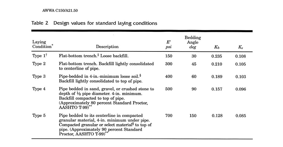
- Kx = deflection coefficient, from Table 2 in AWWA C150 standard E = modulus of elasticity for ductile iron, psi = 24 x 106
- E' = modulus of soil reaction, psi from Table 2 in AWWA C150 standard depending upon trench type
- Δx = design deflection, inches: Δx = 0.03D for cement mortar lining, 0.05D for epoxy lining
2. A Little Quicker Way - Use the Tables Provided in the AWWA C150 Standard
For example, for 24-inch pipe under 13 feet of cover in a Type 3 trench, it will be hydro-tested to 150 psi following installation.
Find the total trench load value (Pv) for the pipe size and depth of cover involved. Use the first row in the table that exceeds the design depth of cover. In this case, that row is 14-feet, and the Pv value is 12.1 psi.
Use the appropriate tables in AWWA C150 to find the dimension ratios (D/t, DR ) for Bending Stress and Deflection Design that first exceed the Pv design value. In this case, that would be 12.1 psi. The D/t and D/t1 values will be different for Bending Stress and Deflection Design and may not appear in the same table within AWWA C150.
In this example, the closest D/t value (dimension ratio) related to a Pv greater than 12.1 for Bending Stress is 126, and the D/t1 for Deflection Design with a Pv value above 12.1 is 98.
The D/t and D/t1 values are the "hard get" in this entire process. Once you have them, it's simply a matter of dividing the pipe's standardized outside diameter by each of these dimension ratios to obtain the net computed thickness for each, Bending Stress (D/t), and Deflection Design (D/t1). Important note - t1 includes the standardized allowance, which needs to be subtracted out later to find the computed net thickness.
In our 24-inch example here, this would equate to:
Bending Stress, net thickness = 25.80 / 126 = 0.20 inches.
Deflection Design, net thickness = (25.80 / 98 ) - 0.08 service allowance = 0.18 inches.
Now we are "apples to apples" comparing Bending Stress results to Deflection Design without the Service Allowance involved.
And lastly, adding the standardized SERVICE ALLOWANCE and CASTING TOLERANCE for the pipe diameter involved determines the Total Calculated Thickness for the given design conditions. This value also referred to as the Minimum Manufactured Thickness, is used to select the proper pipe wall.
The standardized Service Allowance for all diameters of Ductile iron pipe is 0.08 inches.
Concluding our 24-inch example:
Bending Stress, total calculated thickness = 0.20 + 0.08 + 0.07 = 0.35 inches. Deflection Design, total calculated thickness = 0.18 + 0.08 + 0.07 = 0.33 inches.
Given these results, Bending Stress would govern the design between these two, and for 24-inch Di pipe the first available wall class that meets or exceeds 0.35 inches is a Pressure Class 250.
Now check to see if the pipe wall required for INTERNAL PRESSURE containment is not thicker than the BENDING STRESS and/or DEFLECTION DESIGN results.
Pi = design internal pressure, psi = 2 (Pw + Ps) Pw= working pressure, psi
Ps= surge allowance, 100 psi (based on 2 ft/ sec change in velocity)
Pi = 2 (150 +100) = 500psi
t = (Pi D) / 2 S = (500 x 25.80) / 2 x 42,000 = 0.15 inches
computed net thickness for 150 psi design pressure
Add-on the standard allowances for 24-inch Di pipe to obtain TCT for INTERNAL PRESSURE DESIGN.
Net Thickness = 0.15 inches
Service Allowance = 0.08 inches
Casting Tolerance = 0.07 inches
Total calculated thickness = 0.30 inches
Comparing all three results, the BENDING STRESS requirement, in this case, exceeds both the DEFLECTION DESIGN and INTERNAL PRESSURE wall thickness requirements. Therefore, BENDING STRESS is the GOVERNING DESIGN, and PC 250 remains the PROPER FINAL WALL SELECTION
Why is the depth of cover important when installing DI pipe, you ask? See this Iron Strong Blog by Gary Gula to find out.
3. The McWane Pocket Engineer - The Easiest and Most Accurate Way
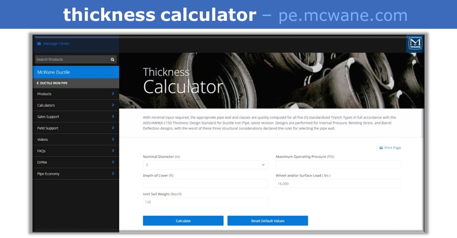
The McWane Pocket Engineer is a free-access no-strings location for ALL THINGS PIPE and other things it takes to make a PIPELINE. Product information, videos, DIPRA literature, FAQs, Field & Sales support, plus 11 unique easy-to-use CALCULATORS available to anyone at pe.mcwane.com or as a FREE DOWNLOAD from Google Play or the App Store.
Simply by entering the pipe diameter, depth of cover, unit soil weight, design pressure, and wheel load - then clicking CALCULATE - does the entire 3-prong AWWA C150 design procedure for all five trench types in a blink. Wheel Load is defaulted at AASHTO H-20 (16,000 lb) but can be changed by the user for other unique loading circumstances. Recommended design pressure is the project's hydrostatic test pressure.
All the calculators on the McWane Pocket Engineer were constructed and operate in full accordance with every design aspect, safety factors, and tolerances of applicable ANSI/AWWA standards, latest editions.
For example, the level of accuracy for instance, that the Thickness Calculator has embedded is demonstrated by the fact that it begins with a presumed dimension ration (D/t) of 700. Yes, 700. Which for a nominal 48-inch pipe equates to a wall thickness of only 0.073 inches (73 mils). A nominal 24-inch DI pipe with a DR of 700 would have a wall of only 0.37 inches (37 mils). Both are ridiculously thin walls for any sized pipe. The program then steps down from 700 by a value of 1 for each iteration/calculation.
The D/t and D/t1 values found as first-sufficient by the Pocket Engineer Thickness Calculator in our 24-inch example were 134 and 104, respectively. So that is more than 1,200 looped calculations to get the answer. That is a week or two by hand or a nanosecond on the Pocket Engineer. Your choice!
Below are the Pocket Engineer Thickness calculations for a 30-inch DI pipe at 200 psi maximum pressure with an 18-foot depth of cover. With the click of a button, you get five complete designs across all the standardized trench types, each in full accordance with every tenet of AWWA C150, latest edition.
| Trench Type |
Trench Type 1 |
Trench Type 2 |
Trench Type 3 |
Trench Type 4 |
Trench Type 5 |
| Pipe Class | 56 | 54 | 52 | 250 | 200 |
| Total Calculated Thickness |
0.60 | 0.54 | 0.47 | 0.40 | 0.38 |
| Governing Design |
Bending Stress |
Bending Stress |
Bending Stress |
Deflection Design |
Internal Pressure |
| Maximum Internal Pressure |
1,654 | 1,444 | 1,234 | 1,103 | 998 |
For more on the difference between Pressure Class and Thickness Class, see this Iron Strong Blog by Jeremy Gwin.
4. Then There is the DIPRA Calculator
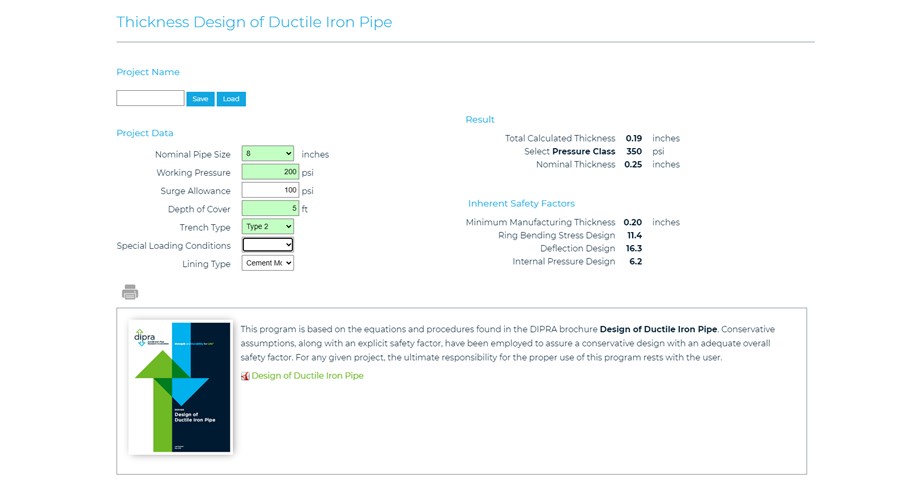
Below is a thickness design example using the Ductile Iron Pipe Research Association (DIPRA) calculator for 8-inch pipe in a Type 2 trench with 5 feet of cover and a design pressure of 200 psi.
Note how high the Inherent Safety Factors are for class 350 pipe in this design scenario.
Ring Bending Stress Design 11.4 = 11 times thicker / stronger than it needs to be.
Deflection Design 16.3 = 16 times thicker/stronger than it needs to be.
Internal Pressure Design 6.2 = 6 times thicker / stronger than it needs to be.
There is NOTHING WEAK about Ductile Iron Pipe!
5. Use the Chart
A "quick look" design analysis can be done using the "Rated Working Pressure and Maximum Depth of Cover," included in the McWane Ductile Brochure. While this chart offers a "will this pipe work in this depth of bury range" answer, it considers only Pressure Class pipe in each available diameter and does not provide any of the "behind the scenes" details and pinpoint accuracy as you get from the McWane Pocket Engineer Thickness Calculator.
Let's revisit the 30-inch pipe example from Option 3 earlier, and a review of the chart shows that PC 250 is indeed adequate for use under 18 feet of cover in a Type 4 trench. See the circled indicators below.
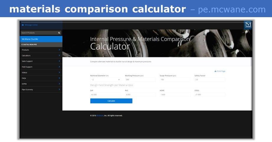
Lastly, just as an interesting note regarding material differences in pipe wall design against internal pressure - the universal hoop stress equation applies to any piping material. To see how the material differences affect maximum pressure containment capabilities, visit the Internal Pressure & Materials Comparison Calculator in the McWane Pocket Engineer.
You might be surprised to see HOW SMALL the hole in the middle gets when calculating the walls required for ALTERNATE PIPE MATERIALS to match the PRESSURE CAPACITIES of relatively thin-walled Ductile iron pipe!
Key Takeaways
Ductile iron pipe design uses a 3-pronged approach. Bending Stress, deflection, and internal pressure are considered. I have outlined five ways to design DI pipe wall:
- Manual use of the equations is lengthy and time-consuming.
- Using the AWWA design tables to find the Pv, etcetera is still time-consuming.
- The Pocket Engineer does all the math in one click—the best.
- DIPRA also has thickness calculators, and they show inherent safety.
- The "Rated Working Pressure and Maximum Depth of Cover chart in the McWane Brochure is also a quick way to find the pressure class, but it does not consider thickness.
If you have any questions about "designing the thickness of DI pipe or anything else related to Ductile iron pipe, please reach out to your local McWane Ductile Sales Representative. From design to installation, we take great pride in providing education and assistance to water professionals throughout the water and wastewater industry.


